Method for manufacturing solid-state thermal neutron detectors with simultaneous high thermal neutron detection efficiency (>50%) and neutron to gamma discrimination (>1.0e4)

Active Publication Date: 2012-09-20
LAWRENCE LIVERMORE NAT SECURITY LLC
View PDF1 Cites 11 Cited by
  • Summary
  • Abstract
  • Description
  • Claims
  • Application Information

AI Technical Summary

Benefits of technology

[0008]One aspect of the invention is a method for manufacturing solid-state thermal neutron detectors with simultaneous high thermal neutron detection efficiency (>50%) and neutron to gamma discrimination (>104). Another aspect is the detector itself. A structure is provided that includes a p+ region on a first side of an intrinsic region and an n+ region on a second side of the intrinsic region. The thickness of the intrinsic region is chosen to achieve a desired neutron to gamma discrimination. Material is removed from (i) one of the p+ region or the n+ region and (ii) the intrinsic layer to produce pillars with open space between each pillar. The pillars have a pitch within a range from about 0.1 μm to about 10 μm and a height within a range from about 10 μm to about 200 μm. A neutron sensitive material comprising 10B fills the open space. One electrode is placed in contact with the pillars and another electrode is placed in contact with the opposite side of the intrinsic layer with respect to the first electrode.
[0009]Generally, the intrinsic layer thickness is less than about 120 μm and more specifically, may be about 50

Problems solved by technology

Moreover, given that the world's supply of 3He is limited, this presents yet another set of critical issues related to strategic and tactical implications, which are of practical importance.
However, improving this metric can result in

Method used


Image

  • Method for manufacturing solid-state thermal neutron detectors with simultaneous high thermal neutron detection efficiency (>50%) and neutron to gamma discrimination (>1.0e4)
  • Method for manufacturing solid-state thermal neutron detectors with simultaneous high thermal neutron detection efficiency (>50%) and neutron to gamma discrimination (>1.0e4)
  • Method for manufacturing solid-state thermal neutron detectors with simultaneous high thermal neutron detection efficiency (>50%) and neutron to gamma discrimination (>1.0e4)

Examples


Embodiment Construction

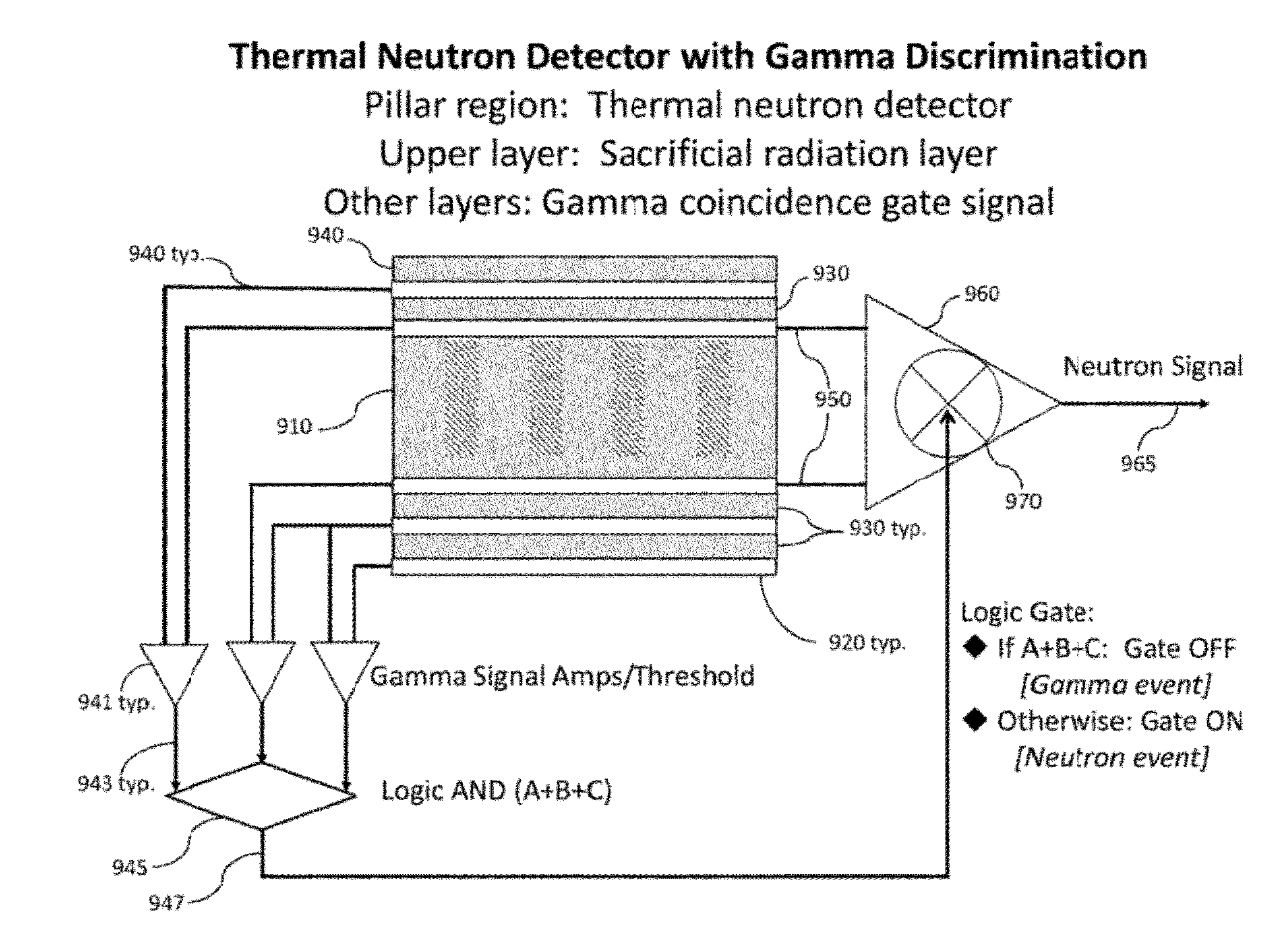
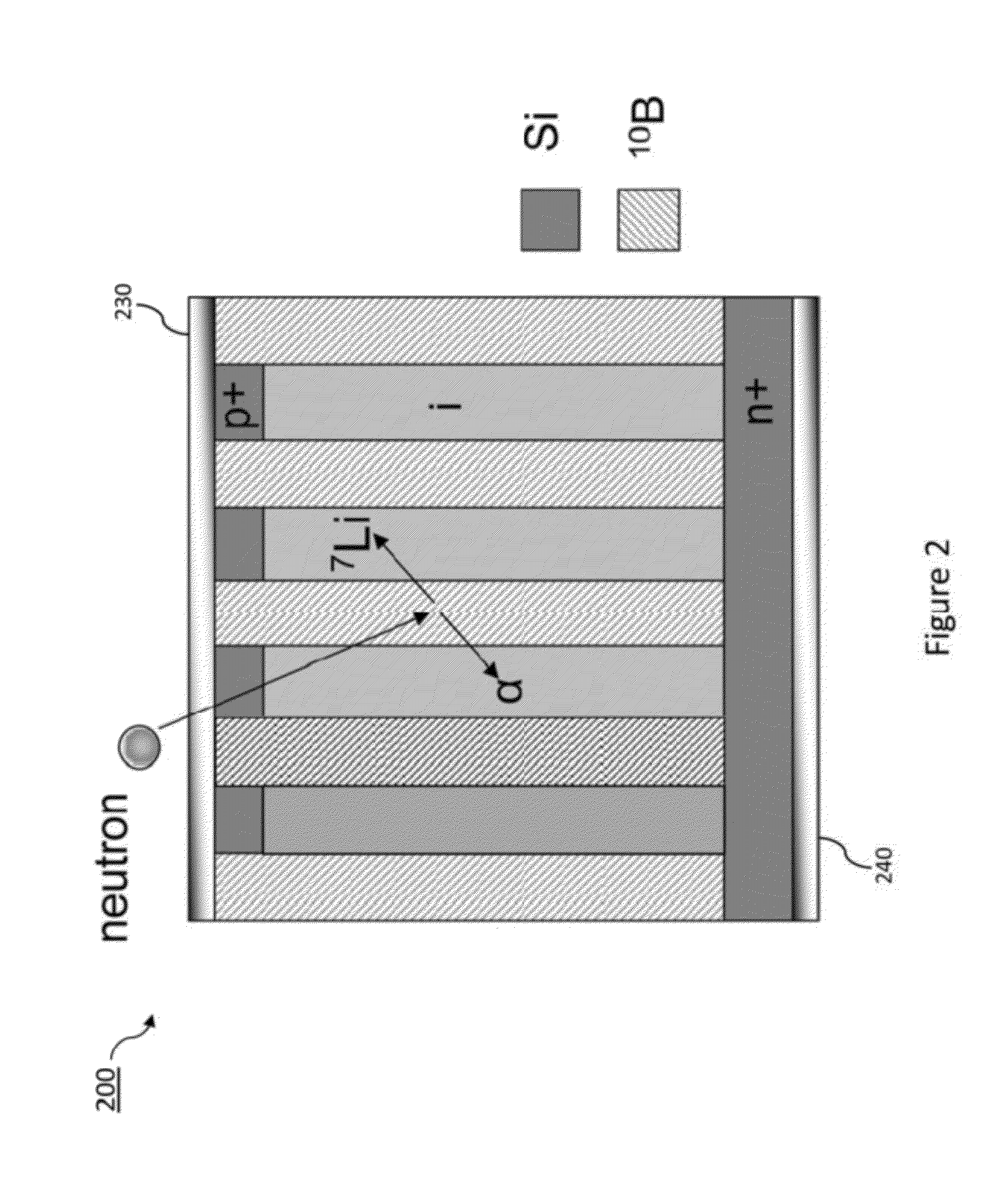
[0059]The platform for thermal neutron detection described herein is based on an array of pillar structured p-i-n semiconductor diodes within which a thermal neutron conversion material, such as 10B, has been interspersed. The salient features of this class of detector are briefly reviewed, followed by embodiments that enhance the detector performance in terms of improved neutron detection sensitivity, concomitant with greater levels of gamma ray discrimination. In the example drawings, the top of the pillar is p+ with n+ as the substrate. The opposite can be done having n+ as the top of the pillar with an p+ substrate. Doping can be done by ion implantation, diffusion or by epitaxial growth. The pillars can be squares, circles, hexagons, etc. While the target design was 50 microns, embodiments of the pillars can be within a broader range, e.g., in the range of 25-100 microns tall.

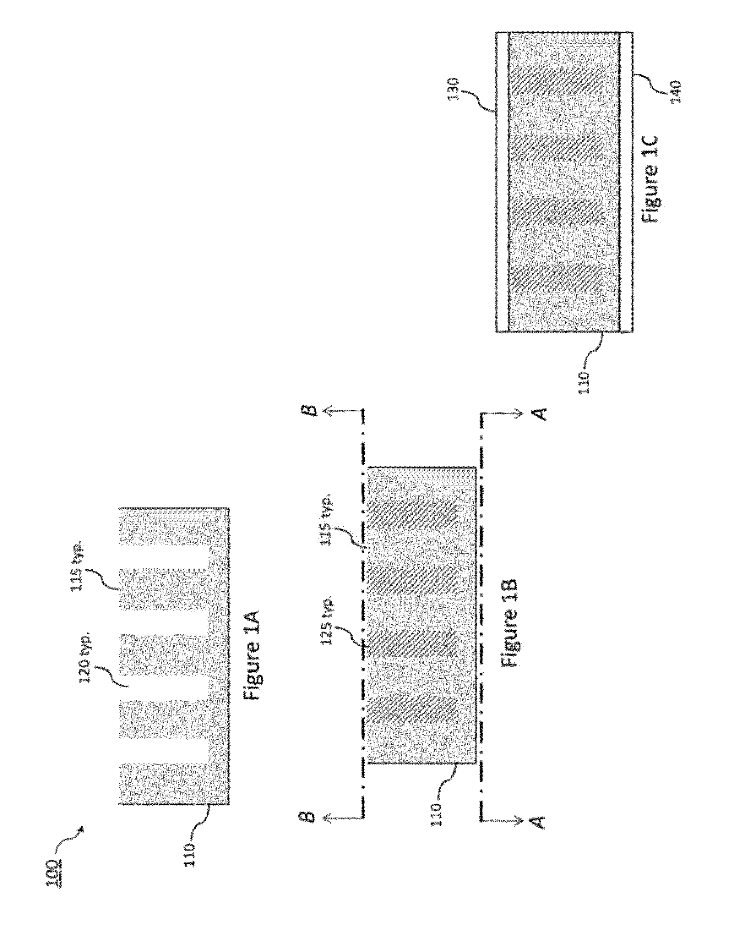
[0060]A basic pillar-based thermal neutron detector is shown in FIGS. 1A, 1B and 1C. A schematic drawin...


PUM


Abstract

Methods for manufacturing solid-state thermal neutron detectors with simultaneous high thermal neutron detection efficiency (>50%) and neutron to gamma discrimination (>104) are provided. A structure is provided that includes a p+ region on a first side of an intrinsic region and an n+ region on a second side of the intrinsic region. The thickness of the intrinsic region is minimized to achieve a desired gamma discrimination factor of at least 1.0E+04. Material is removed from one of the p+ region or the n+ region and into the intrinsic layer to produce pillars with open space between each pillar. The open space is filed with a neutron sensitive material. An electrode is placed in contact with the pillars and another electrode is placed in contact with the side that is opposite of the intrinsic layer with respect to the first electrode.

Description

CROSS-REFERENCE TO RELATED APPLICATIONS[0001]This is a Continuation in Part of U.S. patent application Ser. No. 13 / 014,879, titled “Method To Planarize Three-Dimensional Structures To Enable Conformal Electrodes,” filed Jan. 27, 2011, incorporated by reference. This application claims priority to U.S. provisional No. 61 / 509,023, filed Jul. 18, 2011, incorporated herein by reference. U.S. application Ser. No. 13 / 014,879 is a continuation-in-part of U.S. patent application Ser. No. 11 / 414,288, titled “Semiconductor Materials Matrix for Neutron Detection,” filed Apr. 27, 2006, incorporated herein by reference. U.S. patent application Ser. No. 11 / 414,288 claims priority to U.S. Provisional Patent Application Ser. No. 60 / 675,654, titled “Semiconductor Nano-Materials Matrix for Neutron Detection,” filed Apr. 27, 2005, incorporated herein by reference.STATEMENT REGARDING FEDERALLY SPONSORED RESEARCH OR DEVELOPMENT[0002]The United States Government has rights in this invention pursuant to C...

Claims


Application Information

Patent Timeline
IPC IPC(8): H01L31/115H01L31/18
CPCG01T3/08
Inventor NIKOLIC, REBECCA J.CONWAY, ADAM M.HEINECK, DANIELVOSS, LARS F.WANG, TZU FANGSHAO, QINGHUI
Owner LAWRENCE LIVERMORE NAT SECURITY LLC
Why Eureka
Try Eureka