
Signal device

a signal device and signal technology, applied in the direction of sound producing devices, mining devices, instruments, etc., can solve the problems of unsuitable arrangement and only detectable light sources at extremely limited vision angles, and achieve excellent acoustic signal effect, improve degree of efficacy, and improve the effect of acoustic signal

Inactive Publication Date: 2012-09-20
FHF FUNKE HUSTER FERNSIG
View PDF5 Cites 7 Cited by
  • Summary
  • Abstract
  • Description
  • Claims
  • Application Information

AI Technical Summary

Benefits of technology

[0012]It is an object of the invention to further develop such a signal device in such a manner that the acoustical and particularly the optical warning function as a whole is improved.
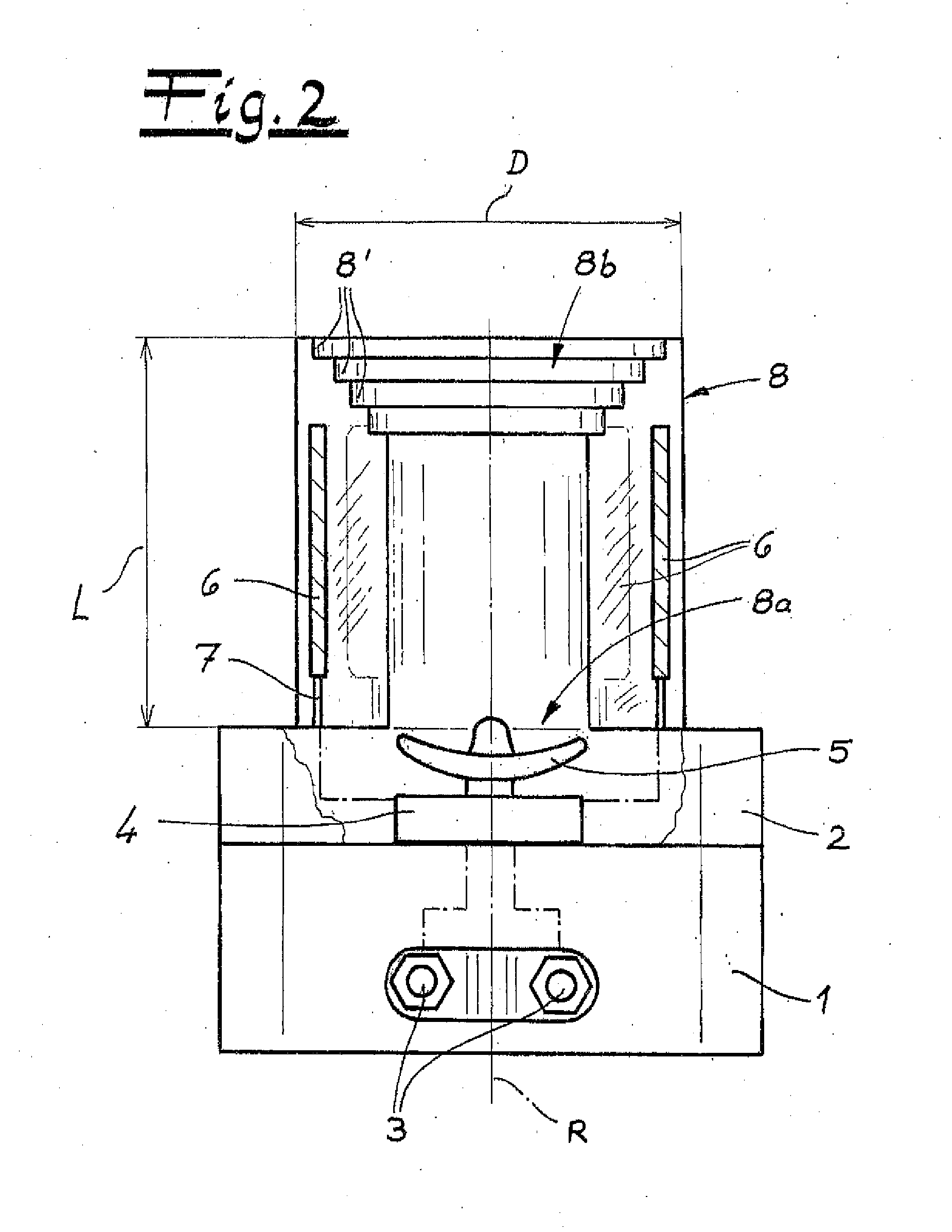
[0017]In detail, it has proven to be advantageous, in this connection, if the sound guidance unit is configured to be transparent. In order to now implement the optical signal function, the sound guidance unit, which is configured to be transparent, can cover the light source or the multiple light sources that are situated behind it. Because of the transparency of the sound guidance unit, the light source or sources can easily be seen through the sound guidance unit and consequently can fulfill its / their signal function without problems. Because of the arrangement of the light source selected behind the sound guidance unit, this source simultaneously experiences protection or a protected arrangement in the interior of the sound guidance unit, which is only open in an upward direction.
[0021]In order to impart the required stability to the sound guidance unit even during robust use, for example underground, in a tunnel, etc., it has proven itself if the sound guidance unit is composed of multiple pipe shells disposed concentric to one another. These individual pipe shells can form a funnel that widens conically toward the outside, in the region of the mouth opening. As a result, the sound emission on the output side of the sound guidance unit is improved.
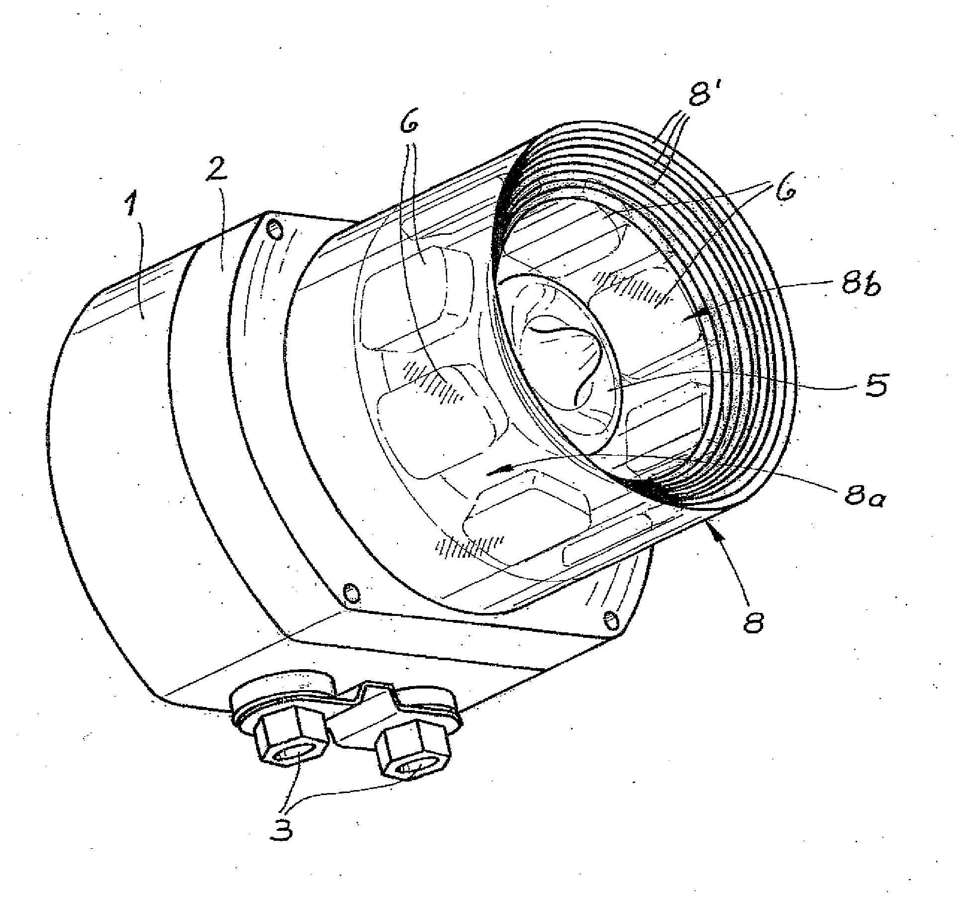
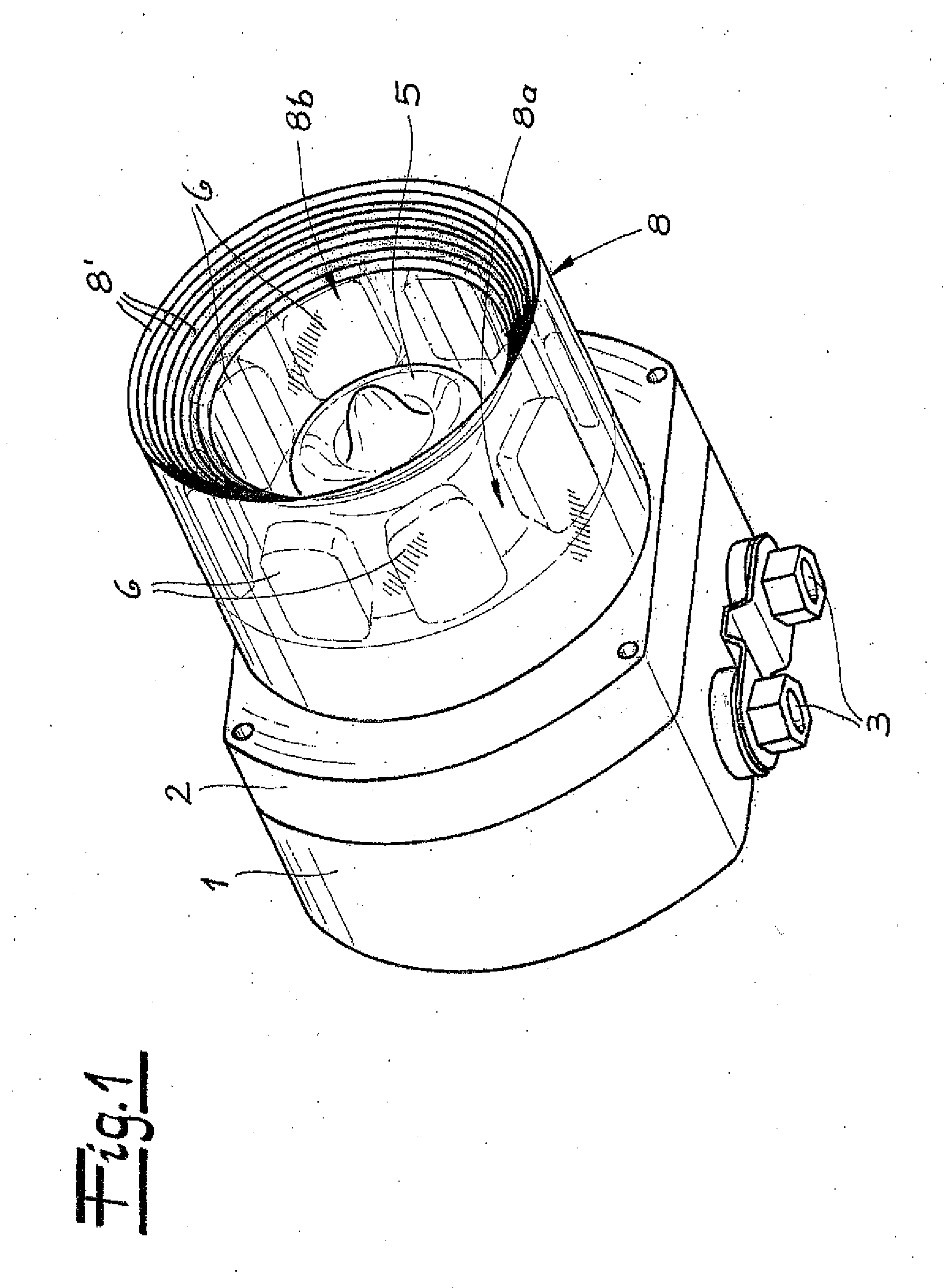
[0028]In the end result, a signal device is made available, which first of all has an excellent acoustical warning function. This excellence is because the channel-like sound guidance unit, which follows the acoustics source with its neck opening and emits the sound produced by the acoustics source to the outside by way of its mouth opening, functions similar to a known loudspeaker horn. The circumstance that the sound guidance unit has an axial length that approximately corresponds to its diameter or actually is less than its diameter contributes to this functionality. As a result, a relatively compact construction is made available, and the horn-like character is emphasized and reinforced in connection with the mouth opening, which is open essentially conically toward the outside or in the manner of a funnel.
[0029]In addition, the sound guidance unit takes on an optical signal function at the same time. Typically, the LEDs placed in the interior of the sound guidance unit, which is open in an upward direction, which are typically disposed in a circle, ensure this functionality. As a result, an optical signal effect is produced in practically all spatial directions, and this feature is of particular significance for the signal effect. The simultaneously horn-like character of the sound guidance unit furthermore ensures that the sound produced by the acoustics source is amplified. This result occurs because the sound guidance unit ensures that the tones emitted by the acoustics source are bundled and emitted in directed manner. This bundling and directed emission is done with an improved degree of efficacy. As a result, the sound guidance unit as a whole functions as a sound amplifier, which clearly improves the acoustic signal effect.

Problems solved by technology

The solution that forms the type at this point, in accordance with DE 30 06 757 A1, however, has the disadvantage that the light source there is detected only under an extremely limited angle of vision.
This arrangement is obviously unsuited to a warning function that can be recognized all around.

Method used


Image

  • Signal device
  • Signal device
  • Signal device

Examples


Embodiment Construction

[0035]Referring now in detail to the drawings, in FIGS. 1 and 2 a signal device is shown that is particularly suitable for use in areas at risk of explosion, underground, in tunnels, etc. For this purpose, the signal device has a housing that is closed or encapsulated, as a whole, which is composed of a lower part 1 and an upper part 2 within the scope of the exemplary embodiment, without being restrictive. From the sectional representation according to FIG. 2, one can see that lower part 1 functions as the base of the housing, and is equipped with cable or line introductions 3, for example. The signal device is supplied with electrical energy and / or data by way of these cable or line introductions 3, or can supplementally or alternatively produce such data itself, as well, and send them to a remote control system.

[0036]Upper part 2 accommodates an electronic circuit 4 that is used to produce acoustical and / or optical signals. For this purpose, an acoustics source 5, which is config...


PUM


Abstract

A signal device, particularly for use in areas at risk of explosion, has a housing, at least one light source, and at least one acoustics source. A sound guidance unit follows the acoustics source with its neck opening and emits the sound produced by the acoustics source to the outside, by way of its mouth opening. The sound guidance unit not only serves to guide sound, but at the same time takes on an optical signal function.

Description

CROSS REFERENCE TO RELATED APPLICATIONS[0001]Applicants claim priority under 35 U.S.C. §119 of German Application No. 20 2011 000 619.0 filed Mar. 17, 2011, the disclosure of which is incorporated by reference.BACKGROUND OF THE INVENTION[0002]1. Field of the Invention[0003]The invention relates to a signal device, particularly for use in areas at risk of explosion. The device has a housing, at least one light source, an acoustics source, and a sound guidance unit that follows the acoustics source with its neck opening and emits the sound produced by the acoustics source to the outside, by way of its mouth opening.[0004]2. The Prior Art[0005]A device that can fundamentally also be used as a signal device and meets the requirements indicated above is presented in DE 30 06 757 A1, which forms the type. This type involves a loudspeaker arrangement that has a loudspeaker membrane, as usual. Furthermore, an optical signal display is assigned to the loudspeaker system. The signal display i...

Claims


Application Information

Patent Timeline
IPC IPC(8): G08B7/00
CPCG08B7/06E21F17/18G10K11/22
Inventor BRONOWICZ, JACEKROEMER, BERNHARD
Owner FHF FUNKE HUSTER FERNSIG
Learn More