Lighting apparatus

a technology of light source and light source, which is applied in the direction of lighting safety devices, lighting and heating devices, semiconductor devices of light sources, etc., can solve the problems of absorbing light from the respective member, prone to fracture of glass, and user discomfort by dazzlement (also known as glare), so as to prevent the scattering of the cover, prolong the service life, and prevent the effect of scattering

Inactive Publication Date: 2012-09-20
SHARP KK
View PDF4 Cites 17 Cited by
  • Summary
  • Abstract
  • Description
  • Claims
  • Application Information

AI Technical Summary

Benefits of technology

[0010]When a lighting apparatus utilizes a light source such as an LED with longer durability and strong optical directivity, it is preferable to provide both measures of preventing the scattering of the cover and reducing glare to the cover of the light source. However, when both measures of preventing scattering and reducing glare are provided by forming the transparent-rubber resilient body or the soft resin film to prevent the scattering of the cover and separately arranging a member for dispersing light from the light source, a problem occurs that respective members absorb the light from a light source and luminance flux is deteriorated.
[0011]The present invention has been made in view of such circumstances. It is an object to provide a lighting apparatus having an anti-scattering film which can prevent the scattering of fragments when the cover fractures and reduce glare without deteriorating luminance flux.
[0012]A lighting apparatus according to the present invention is a lighting apparatus which includes a light source and a light-permeable cover passing light emitted from the light source, and in which an anti-scattering film is arranged on the cover for preventing the scattering of fragments when the cover fractures, wherein the anti-scattering film contains a dispersing agent for dispersing light.
[0013]In the present invention, the anti-scattering film preventing the scattering of fragments when the cover fractures is arranged on the cover passing light emitted from the light source, and the anti-scattering film contains the dispersing agent for dispersing light. Since the anti-scattering film containing the dispersing agent is arranged on the cover, the scattering of fragments of the cover can be prevented when the lighting apparatus is damaged by falling, and the glare can be reduced because light emitted from the light source is dispersed through the dispersing agent in the anti-scattering film. Since the anti-scattering film containing the dispersing agent is arranged on the cover, the deterioration of luminance flux can be prevented as compared to a case of arranging on the cover a member for anti-scattering of fragments when the cover fractures and a member for reducing glare of the light source separately.

Problems solved by technology

However, a glass is prone to be fractured by an impact such as falling.
When a light source having strong optical directivity, such as an LED, is used, a user is likely to feel uncomfortable by dazzlement (also known as glare).
However, when both measures of preventing scattering and reducing glare are provided by forming the transparent-rubber resilient body or the soft resin film to prevent the scattering of the cover and separately arranging a member for dispersing light from the light source, a problem occurs that respective members absorb the light from a light source and luminance flux is deteriorated.

Method used


Image

  • Lighting apparatus
  • Lighting apparatus
  • Lighting apparatus

Examples


first embodiment

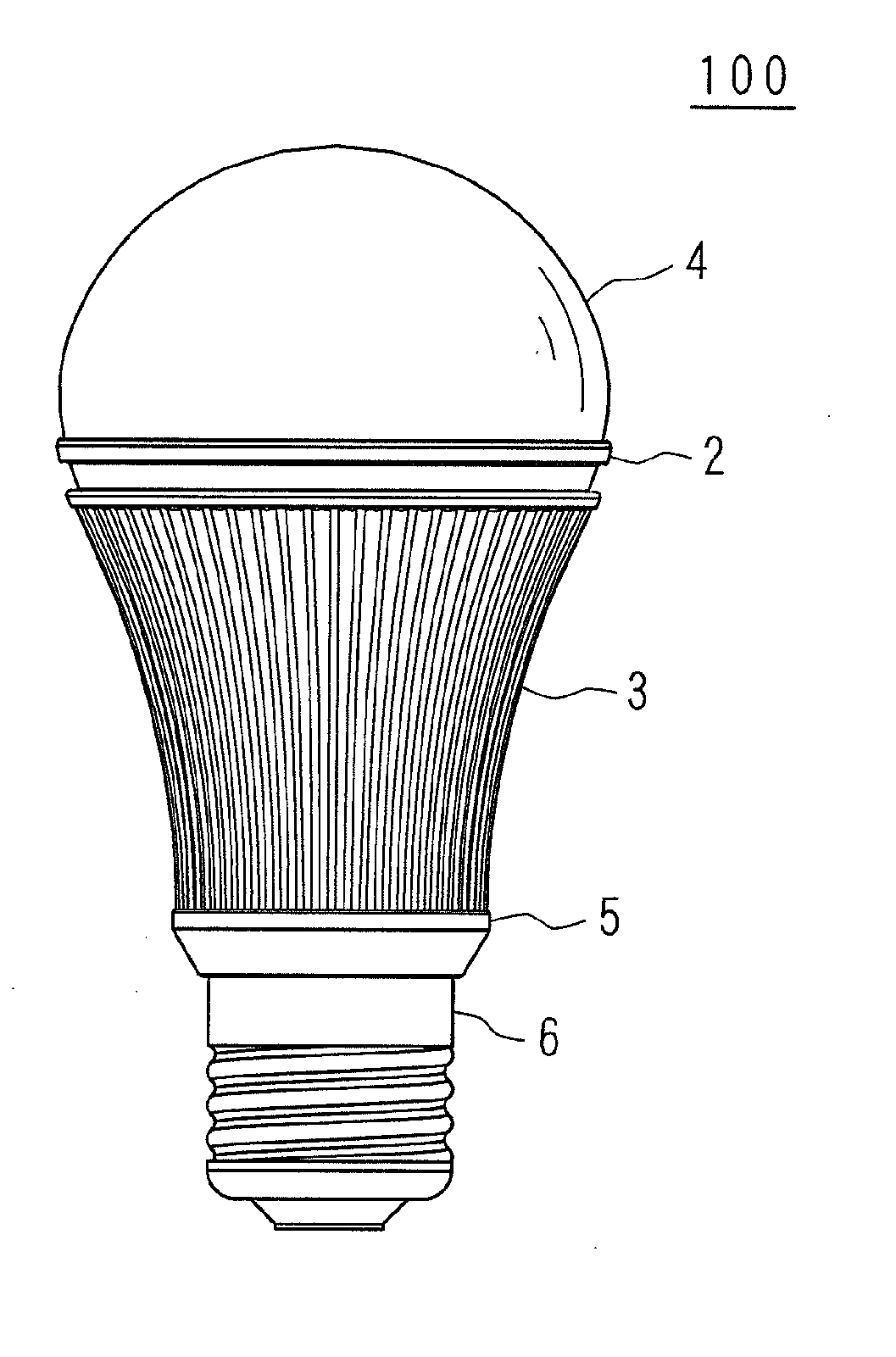
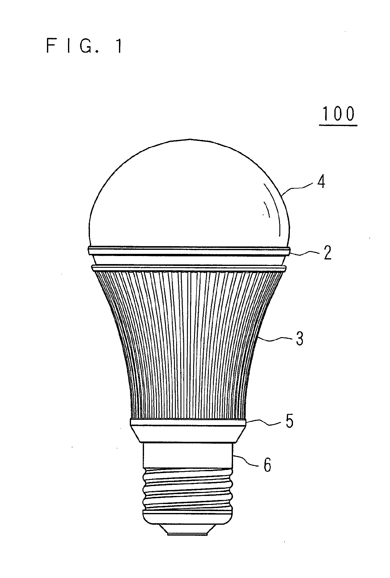
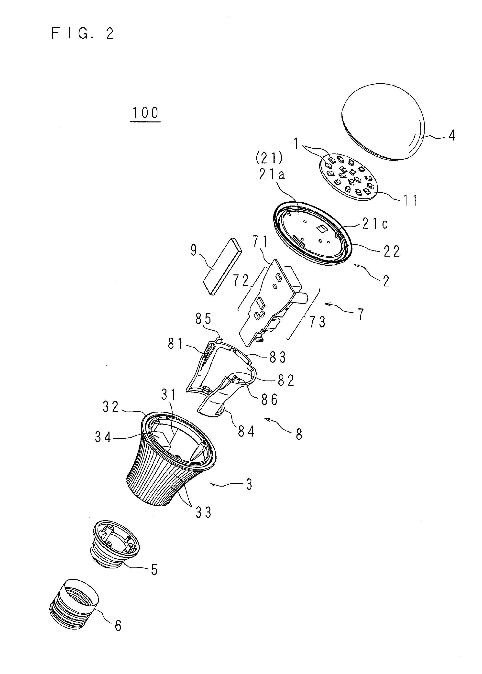
[0032]FIG. 1 is a schematic external view of a lighting apparatus 100 according to the first embodiment of the present invention. FIG. 2 is a schematic exploded perspective view of the lighting apparatus 100 according to the first embodiment. FIG. 3 is a schematic longitudinal sectional view of the lighting apparatus 100 according to the first embodiment. FIG. 4 is a schematic view of an essential part of the lighting apparatus 100 according to the first embodiment.

[0033]In the drawings, the numeral 1 is an LED is utilized as a light source. The LED 1 is a surface mount type LED including, for example, an LED element, a sealing resin which seals the LED element and in which a fluorescent substance is scattered, an input terminal and an output terminal. A plurality of LEDs 1 are mounted on one side of a mounting board 11, which is in the form of a disk.

[0034]The mounting board 11 on which LEDs 1, 1 . . . are mounted is fixed upon a heat sink 2 at the other side as the non-mounting si...

second embodiment

[0057]FIG. 7 is a schematic plan view of an essential part of a lighting apparatus 110 according to the second embodiment of the present invention. In the lighting apparatus 100 according to the first embodiment, the protruding portion 34 protruded in a radially inward direction from a part of the radiation cylinder 31 is formed in the radiation cylinder 31 of the radiator 3; however, in stead of the protruding portion 34, in the present embodiment, an opposite portion 37 having a plane face 37a roughly parallel to the power circuit board 71 of the power supply section 7 and facing to the power circuit board 71 is formed in the radiation cylinder 31. The opposite portion 37 is made of metal such as aluminum, and it is formed in a suitable length along the longitudinal direction of the radiation cylinder 31. The cross section of the opposite portion 37 is in a half-moon shape as shown in FIG. 7. The power supply section 7 is thermally connected to the plane face 37a of the opposite p...

third embodiment

[0059]FIG. 8 is a schematic sectional view of a radiator of a lighting apparatus 120 according to the third embodiment of the present invention. FIG. 9 is a schematic plane view of an essential part of the lighting apparatus 120 according to the third embodiment. In the present embodiment, the refinement of heat absorption is devised to the radiator 3 of the lighting apparatus 110 of the second embodiment. Specifically, regarding the lighting apparatus 120, on the inner surface of a radiator 3a including a plane face 37a of the opposite portion 37, a plurality of grooves 39 whose cross-sectional shapes are U-shaped forms are formed with distributed evenly over the circumferential direction and extending throughout the entire length along the longitudinal direction of the radiator 3a. Since the surface area contacting the air inside the radiator 3a becomes larger, the surface area absorbing the internal air with increasing temperature due to the thermal radiation of the power supply ...


PUM


Abstract

A lighting apparatus includes LEDs and a light-permeable cover passing the light emitted from the LEDs and an anti-scattering film is arranged on the cover for preventing the scattering of fragments when the cover fractures. The anti-scattering film contains a dispersing agent for dispersing light. Since the anti-scattering film containing a dispersing agent is arranged on the cover, when the lighting apparatus is damaged by falling, the scattering of fragments of the cover is preventable, and the glare can be reduced because the light emitted from the LEDs are dispersed through the dispersing agent contained in the anti-scattering film. Since the anti-scattering film containing the dispersing agent is arranged on the cover, the deterioration of luminance flux is preventable as compared to a case of arranging on the cover a member for anti-scattering and a member for reducing glare separately.

Description

[0001]This application is the national phase under 35 U. S. C. §371 of PCT International Application No. PCT / JP2010 / 068269 which has an International filing date of Oct. 18, 2010 and designated the United States of America, all of which are hereby expressly incorporated by reference into the present application.[0002]BACKGROUND[0003]1. Technical Field[0004]The present invention relates to a lighting apparatus including a light source and a light-permeable cover passing light emitted from the light source.[0005]2. Description of Related Art[0006]A lighting apparatus, which is used for illumination of indoor and outdoor, has a light source and a light-permeable cover allowing light to pass, arranged at the light-emitting direction of the light source. When a lighting apparatus in which a light-emitting diode (hereinafter referred as LED) is used as a lighting source, more particularly, since the light source has long operating life, a cover made of glass without long-term deterioratio...

Claims


Application Information

Patent Timeline
Patent Type & Authority Applications(United States)
IPC IPC(8): F21V11/00
CPCF21V3/04F21V25/02F21V23/006F21K9/135F21K9/1355F21Y2101/02F21V29/508F21K9/23F21K9/232F21K9/238F21Y2115/10
Inventor YAMAMOTO, SHOJIAKAO, HIDEYUKI
Owner SHARP KK
Why Eureka
Try Eureka