Pump device for a container for liquid, pasty or foamable cleansing and skin care preparations

a technology of foaming and scalding lips, which is applied in the direction of single-unit apparatus, domestic applications, positive displacement liquid engines, etc., can solve the problems of film hinge damage, and achieve the effect of facilitating the swiveling of sealing lips and high pressur

Inactive Publication Date: 2012-09-20
HUBNER GMBH
View PDF16 Cites 6 Cited by
  • Summary
  • Abstract
  • Description
  • Claims
  • Application Information

AI Technical Summary

Benefits of technology

[0018]According to a second embodiment the outlet valve is constructed as a disk valve and arranged liquid-tight in the outlet connector of the bellows. This disk valve in particular features a valve body, wherein the valve body receives a valve disk through a neck at a distance from the valve body, said valve disk abutting on the outlet connector in radially moveable fashion. From this it is clear that when the bellows is compressed the valve disk forms a radial distance to the outlet connector for the passage for example of the liquid soap. In this connection in addition in particular provision is made that the valve disk exhibits a circumferential rotating sealing lip which is arranged on the neck running in the direction of the neck. That means that the sealing lip of the valve disk runs obliquely, in particular at an angle of circa 45° cm to the connection nozzle. Through the selection of the inclination of the sealing lip consequently the selection of the work angle of the sealing lip to the wall of the connection nozzle support, the force necessary so that in the compression of the bellows the sealing lip swivels radially inward, thus to the neck can be influenced, and hence offers a passage for the medium located in the bellows chamber. It also turns out that in the oblique alignment of the sealing lip to the inside wall of the connection nozzle in the initial state of the bellows the sealing lip abuts with a sufficiently high pressure on the inside wall of the connection nozzle in order to prevent an unintended overrun of the medium located in the bellows chamber of the bellows, for example a liquid soap.
[0019]In this connection it turns out to be advantageous if in the transition from the neck to the valve disk a tangential circumferential groove is provided in order to facilitate the swiveling of the sealing lips for release of the passage for e.g. a hand wash paste.

Problems solved by technology

In this connection there is no risk that the bellows elements will be compressed beyond their dead center position with normal expenditure of force, because this could result in damage to the film hinges.

Method used


Image

  • Pump device for a container for liquid, pasty or foamable cleansing and skin care preparations
  • Pump device for a container for liquid, pasty or foamable cleansing and skin care preparations
  • Pump device for a container for liquid, pasty or foamable cleansing and skin care preparations

Examples


Embodiment Construction

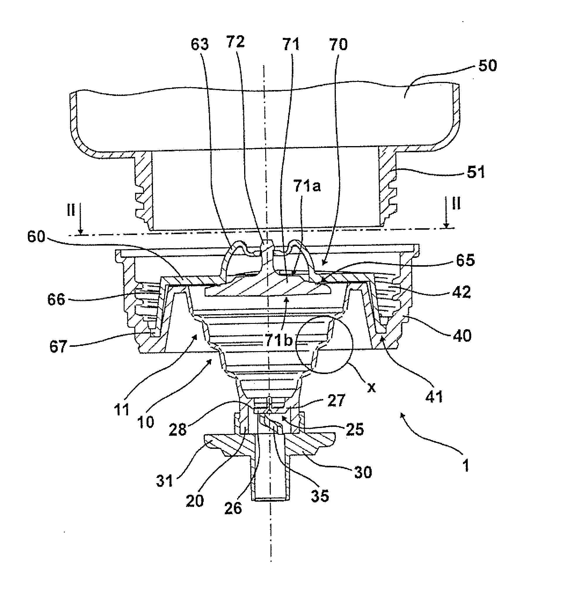
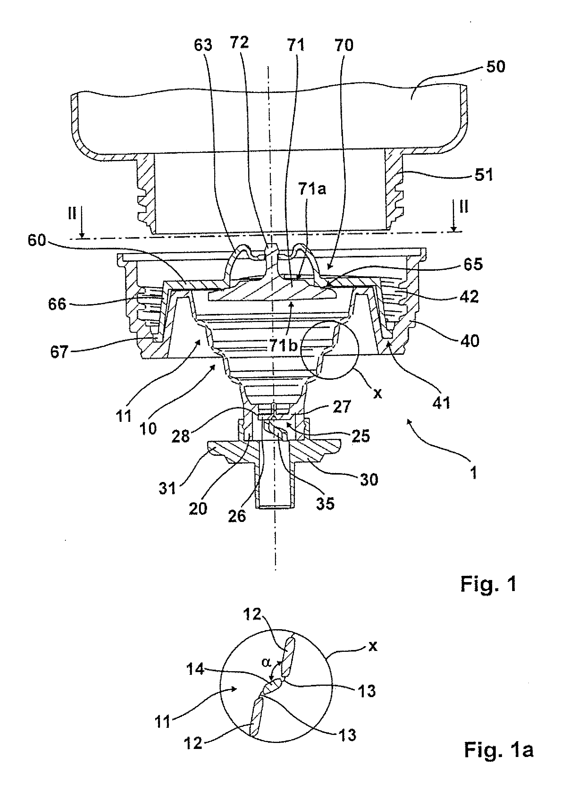
[0035]Taken as a whole the pump device exhibits the reference number 1. The pump device 1 comprises the bellows labeled 10, wherein the bellows has the outlet connector 20 on the outlet side end. The outlet connector 20, which is cylindrical in design, receives the outlet spout labeled 30. The outlet connector 20 shows the outlet valve marked 25, wherein the outlet valve 25 comprises a valve disk 26, which is connected by a web 27 to the outlet connector 20. The outlet spout 30 comprises a protrusion 31 running perpendicular to the longitudinal axis of the pump device, wherein the protrusion 31 can be held by the previously described “catcher clamp”. The outlet spout 30 in addition shows the spring element 35 constructed as a spiral spring, said spring element pressing from below, that is against the direction of the outlet against the valve disk 26, and hence presses the valve disk against the valve seat 28.

[0036]The bellows 10, which forms the bellows chamber 10a, possesses on the...


PUM


Abstract

The subject matter of the invention is a pump device for a container for liquid, pasty or foamable skin care preparations, e.g. for liquid soaps, disinfectants, skin protection pastes or creams, wherein the pump device comprises a conically tapering bellows, wherein the bellows exhibits several bellows elements each having a different diameter, wherein at least one smaller bellows element can be pushed into an adjacent larger bellows element.

Description

CROSS-REFERENCE TO RELATED APPLICATIONS[0001]This application claims priority of German Patent Applications DE 10 2011 014 169.3-16 filed Mar. 16, 2011; DE 20 2011 100 895.2 filed May 19, 2011; and DE 20 2011 105 790.2 filed Sep. 16, 2011, the contents of which are incorporated herein by reference.FIELD OF THE INVENTION[0002]The invention relates to a pump device for a container for liquid, pasty or foamable skin care preparations, e.g. for liquid soaps, disinfectants, skin protection pastes or creams, wherein the pump device comprises a conically tapering bellows, wherein the bellows exhibits several bellows elements each having a different diameter. The skin cleansing preparations can in this connection also contain abrasive bodies.BACKGROUND OF THE INVENTION[0003]Pump devices of the type initially mentioned are sufficiently well known from the prior art. These pump devices are also referred to as suction pumps and in particular as bellows pumps. They are arranged on a container, ...

Claims


Application Information

Patent Timeline
Patent Type & Authority Applications(United States)
IPC IPC(8): F04B43/00
CPCA47K5/1208B05B11/1035
Inventor RICHARDT, MARIOGRIMM, RALF
Owner HUBNER GMBH
Why Eureka
Try Eureka