
Numerical control machine tool

Active Publication Date: 2012-09-20
YAMAZAKI MAZAK KK
View PDF8 Cites 26 Cited by
  • Summary
  • Abstract
  • Description
  • Claims
  • Application Information

AI Technical Summary

Benefits of technology

[0010]Accordingly, it is an objective of the present invention to provide a numerical control machine tool capable of performing an interference check in an initial product machining without increasing the burden on the operator and capable of ensuring safe machining in machining second and subsequent products by reflecting the result of interference checking in the program.Means for Solving the Problem
[0012]According to this configuration, when it is determined that the machining means enters the barrier, movement of the machining means is stopped immediately before or on the boundary line of the barrier. However, if the operator confirms that the machining means actually does not interfere with the holding means, the operator causes the writing means to write a barrier canceling command in the machining program through manipulation of the manipulation means. Accordingly, in the second and subsequent machining of workpieces, the interference check is canceled at a portion where safety has been assured due to no interference between the holding means and the machining means, or, in other words, at a portion where the interference checking means has determined that interference occurs but the barrier canceling command has been written in the initial product machining. As a result, since the barrier is effective in the initial product machining, the operator is allowed to operate without paying attention to the interference check. Further, when the machining is stopped by the interference check, the machining means is stopped in the vicinity of the holding means. This allows the operator to easily confirm whether interference will occur in a subsequent step of the program with reference to the positions of the machining means and the holding means relative to each other. The operator is allowed to reflect the result of judgment to the machining program easily through teaching.
[0018]According to this configuration, in the subsequent and following machining, the interference check on the machining means with the chuck, which is performed by the interference checking means, can be canceled in the process in which safety due to no interference between the chuck and the machining means has been assured, that is, in the process in which the barrier canceling command has been written.

Problems solved by technology

As a result, the operator may erroneously allow an interference between the tool rest and the holding means to occur.
However, this method requires a prolonged time for editing programs in advance and checking for interference in an actual machine tool when in an initial product machining after completion of program writing.

Method used


Image

  • Numerical control machine tool
  • Numerical control machine tool
  • Numerical control machine tool

Examples


Embodiment Construction

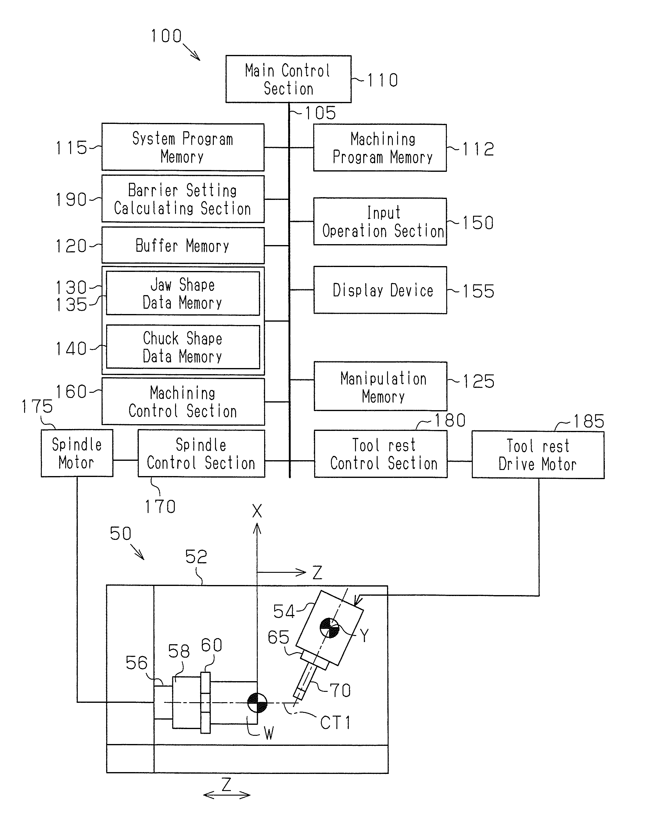
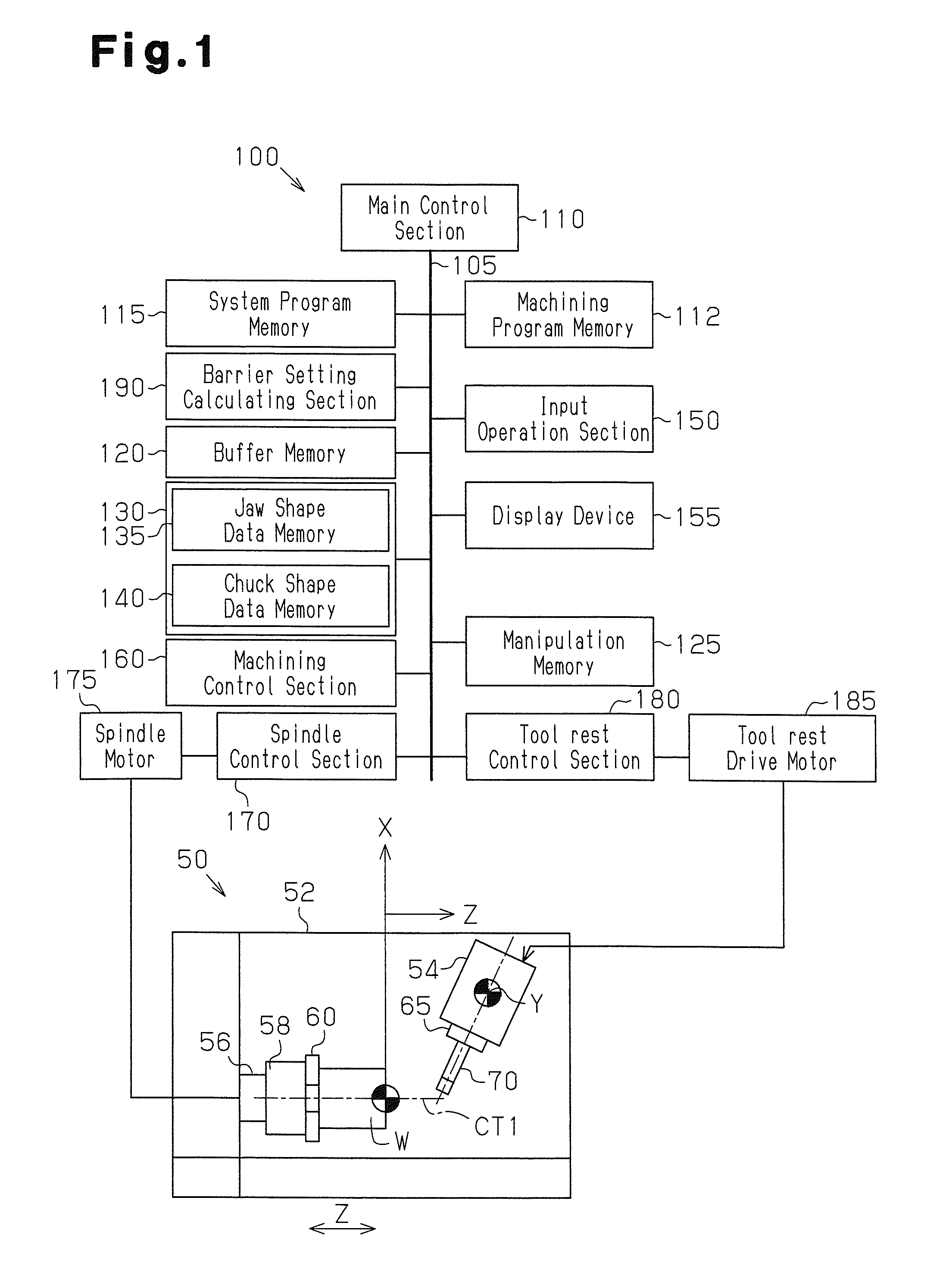
[0030]A numerical control machine tool according to one embodiment of the present invention will now be described with reference to FIGS. 1 to 7. FIG. 1 is a block diagram representing the numerical control machine tool configured with an NC machining apparatus 50 and the system of an NC control unit 100.

[0031]The NC control unit 100 is configured by a computer. The NC control unit 100 has a main control section 110 configured by a CPU. A machining program memory 112, a system program memory 115, a buffer memory 120, a manipulation memory 125, a memory section 130, an input operation section 150 having a keyboard, a display device 155 configured by a liquid crystal display device or the like, various control sections 160, 170, and 180, and a barrier setting calculating section 190 are connected to the main control section 110 through a bus line 105.

[0032]The machining program memory 112, the buffer memory 120, and the manipulation memory 125 each include a random access memory (RAM)...


PUM


Abstract

An NC control unit 100 includes a touch panel display device 155 through which a barrier canceling command is input and a machining control section 160 that performs an interference check for interference between a milling tool 70 and a chuck 58 and jaws 60. When the machining control section 160 determines that interference occurs and stops movement of a tool rest 54, the machining control section 160 writes the barrier canceling command that commands cancelation of the interference check for a process of a machining program where the interference has been determined based on manipulation of the display device 155. When the machining program including the barrier canceling command is carried out to machine subsequent workpieces, the machining control section 160 omits the interference check for the process corresponding to the barrier canceling command.

Description

TECHNICAL FIELD[0001]The present invention relates to a numerical control machine tool.BACKGROUND ART[0002]Conventionally, an interference check is performed in a numerical control machine tool to prevent interference between a tool rest and a holding means for holding a workpiece. The holding means may be a jig such as chuck jaws or a vise. Typically, in an interference check for chuck jaws, a chuck barrier is defined on an X-Z plane for each chuck jaw, and it is determined whether the tool rest or the cutting edge of the cutter enters the chuck barriers, while the tool rest or a cutter of a tool is moved on the X-Z plane (see Patent Document 1). Parameters necessary for setting chuck barriers are set in advance before shipment of the numerical control machine tool. As a result, simply by setting the jaw shape, a user can perform an interference check.[0003]In case of milling a workpiece, the cutting edge of a tool may have to enter a gap between two jaws. In this case, an interfer...

Claims


Application Information

Patent Timeline
IPC IPC(8): G05D3/00
CPCG05B19/4061G05B2219/49157G05B2219/35316G05B2219/49147
Inventor KIKATA, KAZUHIROKIMURA, MORIKUNIIKEDA, SACHIO
Owner YAMAZAKI MAZAK KK
Learn More