Method of detecting an inter-axis offset of 6-axis robot

a technology of inter-axis offset and robot, which is applied in the direction of electric programme control, program control, instruments, etc., can solve the problems of no proposal for a method of measuring and compensating for inter-axis offset, and nothing that satisfies absolute position accuracy, so as to improve the absolute position accuracy

Active Publication Date: 2012-09-20
DENSO WAVE INC
View PDF12 Cites 67 Cited by
  • Summary
  • Abstract
  • Description
  • Claims
  • Application Information

AI Technical Summary

Benefits of technology

[0010]However, up to the present, there has been no proposal for a method of measuring and compensating for the inter-axis offset. Hence it is desired to provide a method of measuring and compensating for an inter-axis offset in a 6-axis robot, so as to improve the absolute position accuracy of the robot.
[0013]Thereafter, X-Y coordinate values of the measurement point at the plurality of positions on the reference coordinate are obtained, the obtained X-Y coordinate values of the measurement point are plotted on the X-Y plane of the reference coordinate, segments interconnecting the plotted points are put as measurement dependence segments, and a length of a perpendicular line from the origin of the reference coordinate onto a linear lines obtained by extending the measurement dependence segments is then obtained as an amount of deviation. Then, the obtained amount of deviation corresponds to a sum of inter-axis offsets of the second, third, and fifth rotation joints. By the inter-axis offsets obtained in the way described above, for example, by correcting DH (Denavit-Hartenberg) parameters, it is possible to improve the absolute position accuracy.

Problems solved by technology

However, results of the experiment have showed nothing that satisfies the absolute position accuracy originally expected by the inventor.
However, up to the present, there has been no proposal for a method of measuring and compensating for the inter-axis offset.

Method used


Image

  • Method of detecting an inter-axis offset of 6-axis robot
  • Method of detecting an inter-axis offset of 6-axis robot
  • Method of detecting an inter-axis offset of 6-axis robot

Examples


first embodiment

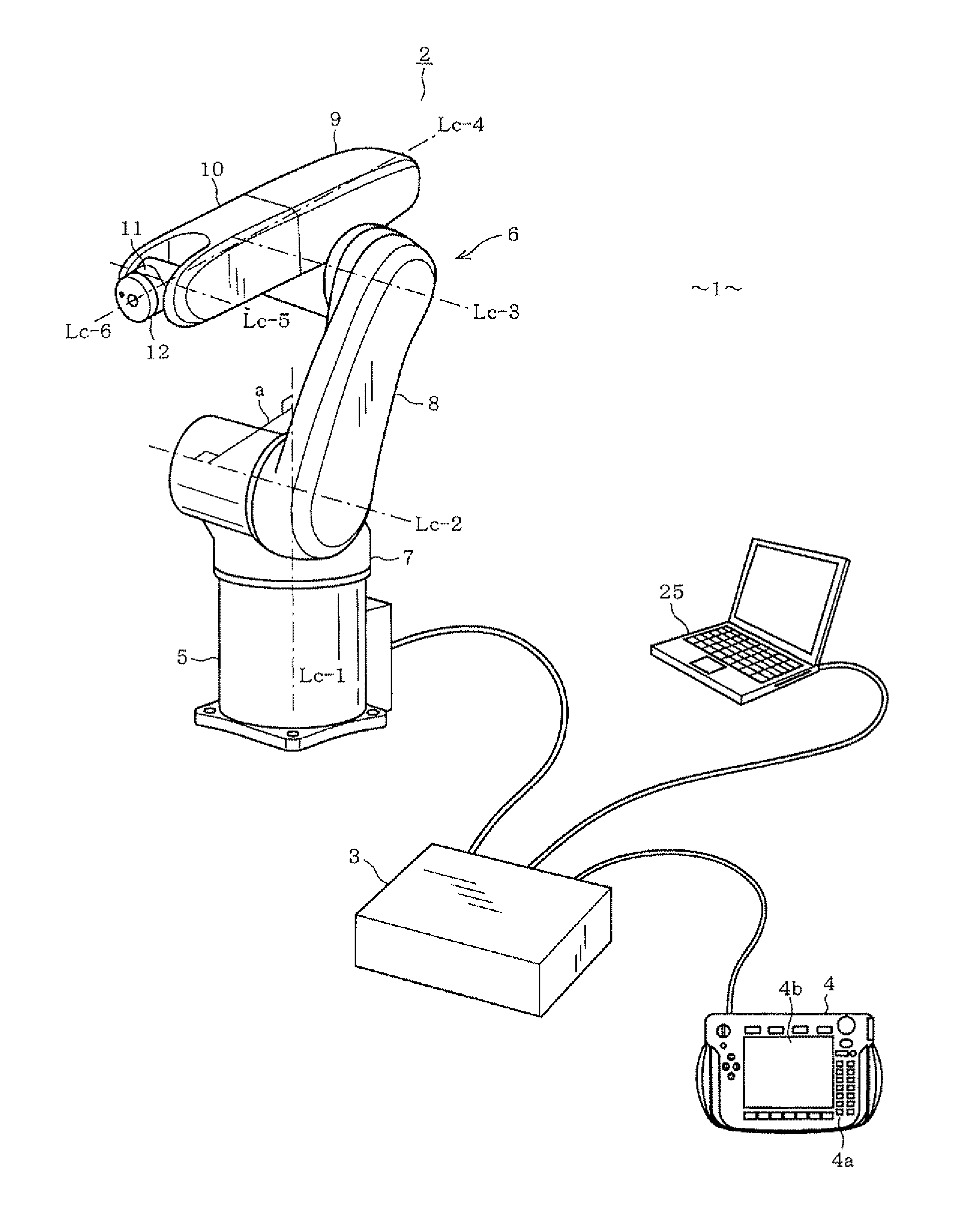
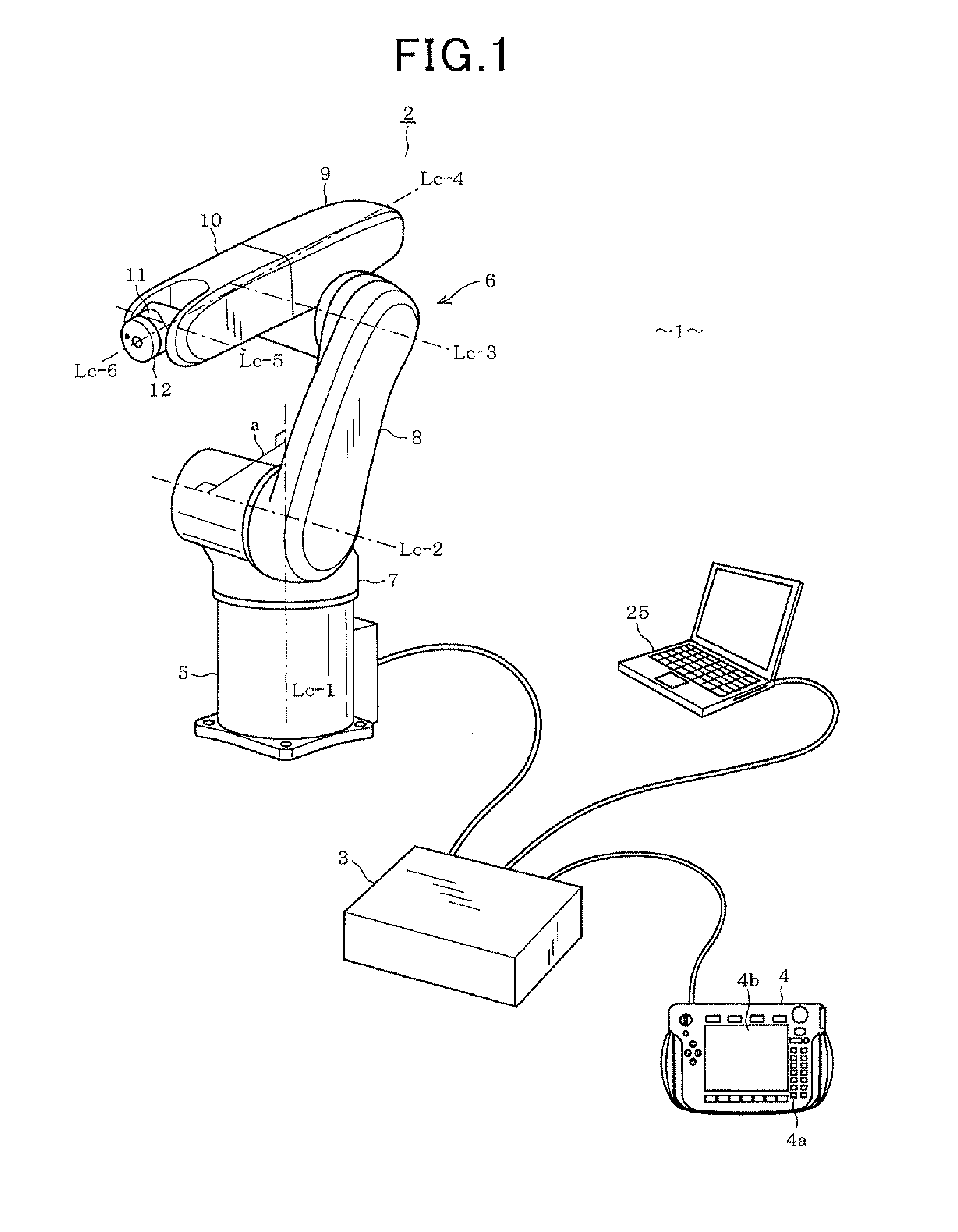
[0067]Hereinafter, a first embodiment of the present invention will be described with reference to FIGS. 1 to 16. FIG. 1 shows a 6-axis multiple vertical rotation joint type robot apparatus 1. The robot apparatus 1 includes a 6-axis multiple vertical joint type robot (hereinafter, simply referred to as “robot”) 2, a control unit (robot control means) 3 for controlling the operation of the robot 2, and a teaching pendent (manual operating means) 4 connected to the control unit 3 to operate the robot 2 through a manual handling.

[0068]The robot 2 includes a base (base link) 5 fixed to an installation surface, such as a floor of a factory, and a robot arm 6 connected in contact with the base 5. The robot arm 6 includes a shoulder (first link) 7, a lower arm (second link) 8, a first upper arm (third link) 9, a second upper arm (fourth link) 10, a wrist (fifth link) 11, and a flange (sixth link) 12, which are sequentially connected to one another through their respective rotation joints, ...

second embodiment

[0124]FIG. 17 shows the second embodiment of the present invention. In not only the second embodiment and subsequent embodiments but also modifications thereof, the components which are similar or identical to those described in the first embodiment will be given the same reference numerals for the sake of a simplified explanation.

[0125]In this embodiment, although the reference coordinate Rb is obtained in the same way as in the first embodiment, a different method is employed in obtaining the inter-axis offset.

[0126]In the present embodiment, when a plurality of positions are set as target positions of movement and an end effector has been moved to the plurality of position's, the inter-axis offset is obtained based on a difference between a target position of movement and an actually moved position. That is to say, the inter-axis offset is put as “0” and a plurality of positions on the reference coordinate Rb are optionally selected as target positions of movement. Further, since...

third embodiment

[0132]FIGS. 19 to 21 show the third embodiment of the present invention. Hereinafter, constructions of the present embodiment different from those of the first embodiment will be described. In the present embodiment, the light emitting diode 24 is not attached to the end effector (center of a distal end surface of the flange 12), but is attached to a predetermined position on the flange 12 spaced apart in the direction of diameter from the rotation center line Lc-6 of the sixth rotation joint J6.

[0133]In the present embodiment, as shown in FIG. 19, a support 26 on which the light emitting diode 24 is mounted is attached to a predetermined position spaced apart from a center P of a distal end surface of the flange 12.

[0134]In order to set the reference coordinate Rb on the camera coordinate Rc, first, the fifth axis Lc-5, which is the rotation center line of the rotation shaft 14 of the fifth rotation joint J5, is maintained in parallel to the second axis Lc-2 and the third axis Lc-3...


PUM


Abstract

In a 6-axis robot, as an example, an inter-axis offset can be measured and calibrated. A light emitting diode is installed on an end effector, and the end effector is located on a plurality of target positions of movement on the axis X (Xb) of a robot coordinate. Then, the position of the light emitting diode is measured by a three-dimensional gauge, and an inter-axis offset F is detected based on an error between the target positions of movement and actually moved positions. For the inter-axis offset F, DH parameters are calibrated.

Description

CROSS-REFERENCE TO RELATED APPLICATION[0001]This application is based on and claims the benefit of priority from earlier Japanese Patent Applications No. 2011-060619 filed Mar. 18, 2011; No. 2011-142825 filed Jun. 28, 2011; and 2011-178962 filed Aug. 18, 2011, the descriptions of which are incorporated herein by reference.BACKGROUND[0002]1. Field[0003]The present invention relates to a method for detecting an inter-axis offset of a 6-axis robot, which detects and compensates for an offset between a first rotation joint and a second, third, or fifth rotation joint, which have rotation axes perpendicular to each other.[0004]2. Description of Related Art[0005]A 6-axis robot is configured to convert given position data, which is expressed by fixed three-dimensional orthogonal coordinates, to angle data for a rotation joint of the robot and move an end effector (i.e., hand) of the robot to a position indicated by the position data. In this event, if an error occurs in a link (arm) length...

Claims


Application Information

Patent Timeline
Patent Type & Authority Applications(United States)
IPC IPC(8): G05B19/04
CPCG05B2219/40588B25J9/1692
Inventor KAGAWA, NAOYA
Owner DENSO WAVE INC
Why Eureka
Try Eureka