Eureka AIR delivers breakthrough ideas for toughest innovation challenges, trusted by R&D personnel around the world.

Door closer comprising device for preventing a spring-back

a technology for preventing a spring-back and a door closer, which is applied in the direction of valve operating means/releasing devices, wing accessories, and tools, etc., can solve the problems that the traction of the closer springs whenever the door is opened cannot be expected from children, ill persons or senior citizens, in particular, and achieves a slender structure. , the effect of low cos

Active Publication Date: 2012-09-27
DORMAKABA DEUT GMBH
View PDF12 Cites 9 Cited by
  • Summary
  • Abstract
  • Description
  • Claims
  • Application Information

AI Technical Summary

Benefits of technology

[0006]It is an object underlying the present invention to provide a door closer which has a very slender structure while being manufactured at low costs, and which is consequently also applicable as an integrated door closer, e.g. in a door frame or a door. In addition, the door closer is configured to include a locking function or a free-swing-function, and a rebound shall be avoided as far as possible.
[0009]Preferably, the door closer including a free-swing-function is used in facilities for handicapped persons, apartments for senior citizens, or nursery schools as well as for safeguarding fire protection doors. In combination with a fire alarm system, the closing of said doors is secured for avoiding a propagation of smoke and fire, without exposing the users of the door to a constant opening moment of prior art door closers. In particular in case of fire protection doors, very strong closer springs have to be used, such that a safe closing of the door can be guaranteed also in case of an air draft in the corridors. The tensioning of such closer springs whenever the door is opened cannot be expected from children, ill persons or senior citizens, in particular. In this case, the free-swing-function enables that the closer spring is biased only once and remains biased until a possible emergency case. The present door closer can be inserted invisibly into the door leaf or in the door frame due to its very slender overall width, such that no optical drawback occurs and it is protected against demolition by vandalism.
[0016]Preferably, the spring-loaded check valve locks toward the space becoming smaller. According to one embodiment of the invention, a hydraulic pressure is built up and maintained in the lock compartment to arrest the closer spring. For a pressure generation in the lock compartment, all elastic members contained therein, e.g. seals, residue air or also the hydraulic oil itself, are compressed accordingly. This results in an undesired loss of volume. The closer spring tension piston compensates for this loss of volume, however, performs a small subsequent stroke. This subsequent stroke is transmitted to the piston rod and consequently to the piston assembly, the output shaft and the door. This results in a turning back of the door by several degrees when using the locking function. In case the free-swing-function is used, the subsequent stroke has the effect that the door cannot be opened completely to the desired position. This undesired effect is referred to as rebound, which becomes noticeable in particular in case of restricted door opening angles determined by structural conditions. This effect is especially pronounced in case of door closers with cam technology due to the small rotary angle-stroke-ratio. The arrangement proposed herein, including the spring-loaded check valve, reduces said rebound by pumping the hydraulic oil, being actively pre-pressurized, from a pressure space becoming smaller in the opening direction through the third check valve into the lock compartment during the opening process. Therewith, a relative opening resistance, similar to a opening damping, is intentionally generated in order to bias the hydraulic oil and to obviate compression-set-characteristics. In pre-known arrangements, the hydraulic oil is only passively suctioned from the tank compartment into the pressure compartments during the opening process, which may partially even generate a slightly negative pressure. The elastic members therewith completely relax and require a relatively high compensation volume including a corresponding subsequent stroke in order to enable again a holding pressure sufficient for the spring force. In this case, a maximum pressure difference exists. In the case described herein, the compression-set-characteristics of the elastic members in the lock compartment therefore occur during a slight pressure difference, as a result of which the loss of volume and thus the subsequent stroke is smaller. Accordingly, the turning back or the rebound of the piston assembly from the intended position is considerably smaller.
[0019]Further, it is advantageous that the space becoming smaller is closed, except for the check valve, during the opening process.

Problems solved by technology

The tensioning of such closer springs whenever the door is opened cannot be expected from children, ill persons or senior citizens, in particular.

Method used


Image

  • Door closer comprising device for preventing a spring-back
  • Door closer comprising device for preventing a spring-back
  • Door closer comprising device for preventing a spring-back

Examples


first embodiment

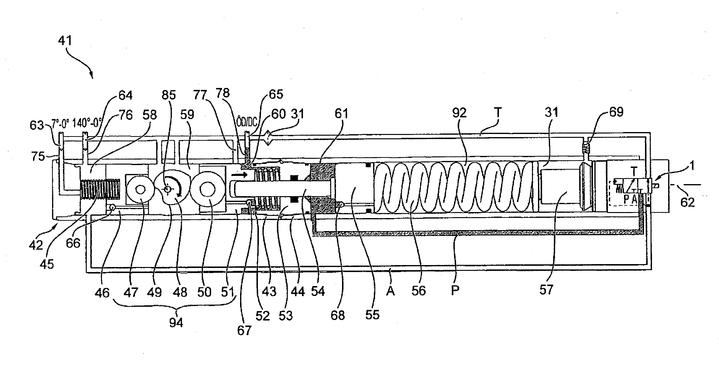
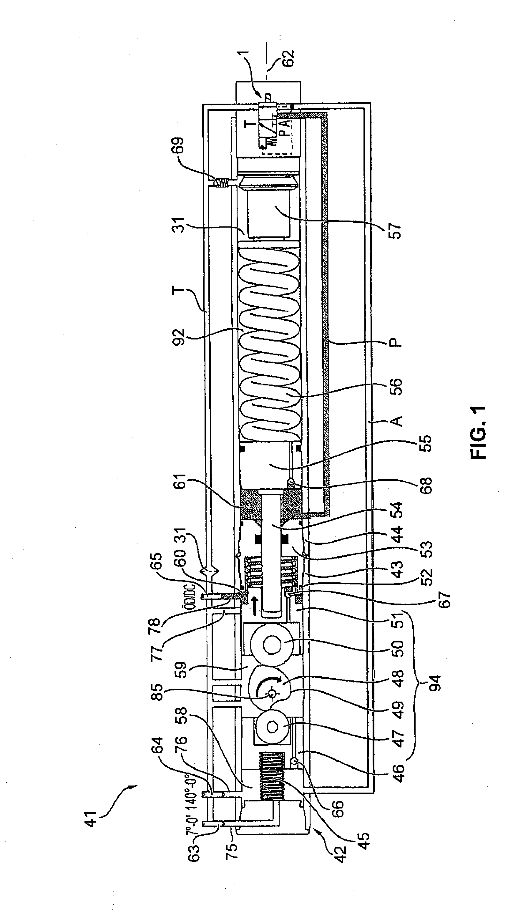
[0041]In the following, the basic structure as well as the hydraulic control and the function of a door closer 41 is explained with reference to FIG. 1.

[0042]The door closer 41 extends along a longitudinal door closer axis 62. The door closer 41 comprises a door closer housing 42 which in turn consists of a first door closer housing part 43 and a second door closer housing part 44. In FIG. 1, the various hydraulic lines are shown to be outside the door closer housing 42. This illustration, however, is only given for facility of inspection. In practice, the hydraulic lines are integrated into the door closer housing 42. In the following, the structure of the door closer 41 along its longitudinal door closer axis 62 is explained from left to right. A first pressure spring 45 is supported against the door closer housing 42, in particular against a front face of the first door closer housing part 43. The first pressure spring 45 pushes a piston assembly 94. This piston assembly 94 is g...

second embodiment

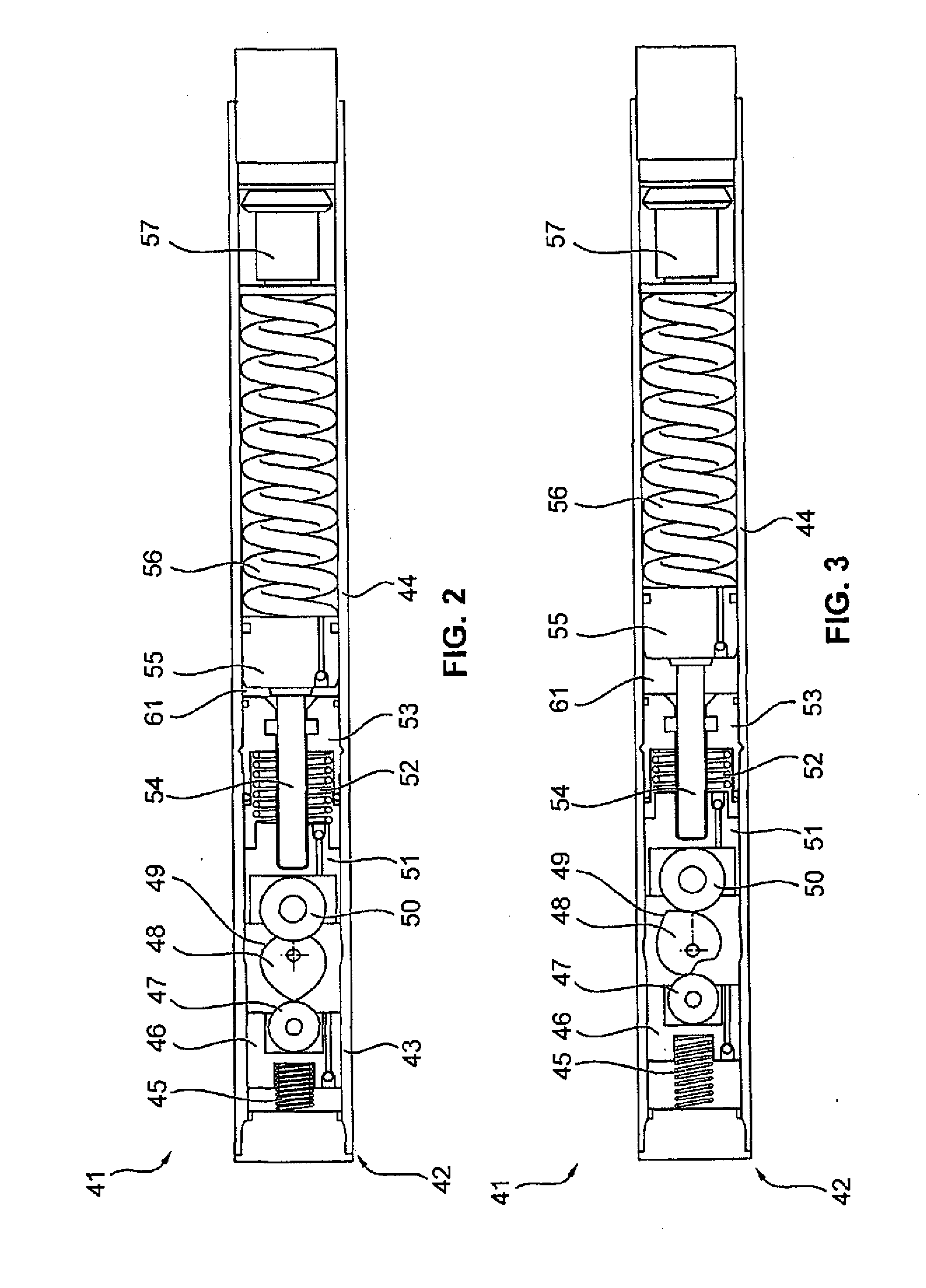
[0051]FIGS. 7 and 8 show a door closer 41 according to a Identical components or components identical in function are designated with identical reference numerals in all embodiments. FIG. 7 shows a door closer 41 during biasing of the closer spring 56. In FIG. 8, the lock compartment 61 is hydraulically blocked through the pressure line P. Consequently, the closer spring tension piston 55 and the closer spring 56 remain in their tensed positions. The piston assembly 94 and the door are freely swingable.

[0052]Apart from the difference described in the following, the second embodiment corresponds to the first embodiment. In contrast to the first embodiment, an additional piston 95 is arranged between the separating wall 53 and the piston assembly 94, in particular the opening piston 51, in the second embodiment. The additional piston 95 is fixedly connected to the piston rod 54 for transmitting a translational motion. The first front face 74 is formed frontally at the additional pist...

third embodiment

[0054]The piston assembly 94 proposed in FIGS. 9 and 10 replaces the piston assembly 94 of FIGS. 1 to 7, in particular the damper piston 46 including the first cam disc 47 and the opening piston 51 including the second cam disc 50. The output shaft 48 remains unchanged. Due to the use of the piston assembly 94 the first pressure spring 45 and the second pressure spring 52 are not required, however, can be used in addition.

[0055]FIG. 9 shows the piston assembly 94, wherein the damper piston 46 and the opening piston 51 are connected by a first tie rod 81, a second tie rod 82, a third tie rod 83 and a forth tie rod 84. The four tie rods 81 to 84 are arranged in parallel with the longitudinal door closer axis 62. In addition, the four tie rods 81 to 84 are arranged at four corners of a square or rectangle to be considered for the purpose of explanation only. The output axis 85 of the output shaft 48 passes through the section point of the diagonals of said square or rectangle. Due to ...


PUM


Abstract

A door closer, in particular a hinge door closer, including a locking function or free-swing function, having a door closer housing, an output shaft to be connected to a door, a piston assembly connected to the output shaft and guided in the door closer housing, a closer spring, a piston rod adapted to connect the piston assembly to the closer spring, a hydraulic lock compartment adapted to lock the closer spring, and a spring-loaded check valve arranged between the lock compartment and a space becoming smaller during the opening process of the door, in particular an accommodating space for the closer spring. The spring-loaded check valve locks toward the space becoming smaller.

Description

CROSS REFERENCE TO RELATED APPLICATIONS[0001]This is a U.S. national stage of application No. PCT / EP2010 / 007251, filed on 30 Nov. 2010. Priority is claimed on German Application No. 10 2009 056 265.6 filed 1 Dec. 2009 and German Application No. 10 2010 013 853.3 filed 1 Apr. 2010, the contents of which are incorporated here by reference.BACKGROUND OF THE INVENTION[0002]1. Field of the Invention[0003]The invention relates to a door closer that reduces or avoids a springback or rebound.[0004]2. Description of Prior Art[0005]In the state of the art, a differentiation is made between door closers and door drives. In case of door closers, the door has to be opened manually by a person. During the opening process, energy is stored, e.g. in a closer spring, and the door closer is able to close the door using the stored energy. In contrast, the door drive is an assembly that automatically opens and closes the door by an additional auxiliary energy, e.g. by a motor or hydraulics. In particul...

Claims


Application Information

Patent Timeline
Patent Type & Authority Applications(United States)
IPC IPC(8): E05F3/22
CPCE05F3/104Y10T16/593F16K31/0627F16K31/0693E05Y2900/132Y10T16/2793Y10T16/27Y10T16/276Y10T16/2766Y10T16/2788Y10T16/2769Y10T16/2771Y10T16/2796Y10T16/56E05F3/223E05Y2201/638E05Y2600/634Y10T137/87917
Inventor BIENEK, VOLKERWIEMANN, SABINEPABST, THOMAS
Owner DORMAKABA DEUT GMBH
Why Eureka
Eureka Blog
Learn More