Braking device with hidden hydraulic cylinder

a technology of hydraulic cylinder and braking device, which is applied in the direction of mechanical control device, bicycle brake, instruments, etc., can solve the problems of wear or break, inconvenience for users in use, and inability to meet the user's demand for high-quality products, so as to save space and prevent leakage

Inactive Publication Date: 2012-09-27
TEKTRO TECH
View PDF7 Cites 48 Cited by
  • Summary
  • Abstract
  • Description
  • Claims
  • Application Information

AI Technical Summary

Benefits of technology

[0008]The object of the present invention is to provide a braking device with a hidden hydraulic cylinder, in which the hydraulic cylinder is hidden inside the body and protected by a casing made of plastics, rubber or light alloy in order to save space and prevent leakage due to unexpected collision.

Problems solved by technology

In order to meet the requirements for innovation and special purpose such as bicycle race, a conventional braking device has not satisfied for the user's demand of pursuing high-quality product.
Since the hydraulic cylinder must be mounted on an external surface of the bicycle, there causes inconvenience for the user in use and it is easy to cause leakage if any unexpected collision occurs.
The tube is fixedly mounted in manner of being bent, which intends to cause wear or breaks and thus leakage.
Therefore, the brake cannot fit to different types of bicycles, limiting its application.

Method used


Image

  • Braking device with hidden hydraulic cylinder
  • Braking device with hidden hydraulic cylinder
  • Braking device with hidden hydraulic cylinder

Examples


Embodiment Construction

[0019]The aforementioned illustrations and following detailed descriptions are exemplary for the purpose of further explaining the scope of the present invention. Other objectives and advantages related to the present invention will be illustrated in the subsequent descriptions and appended tables.

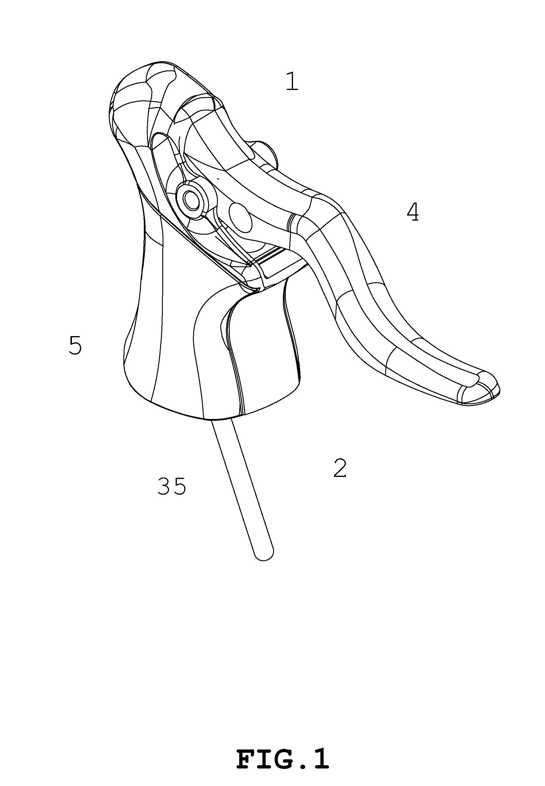
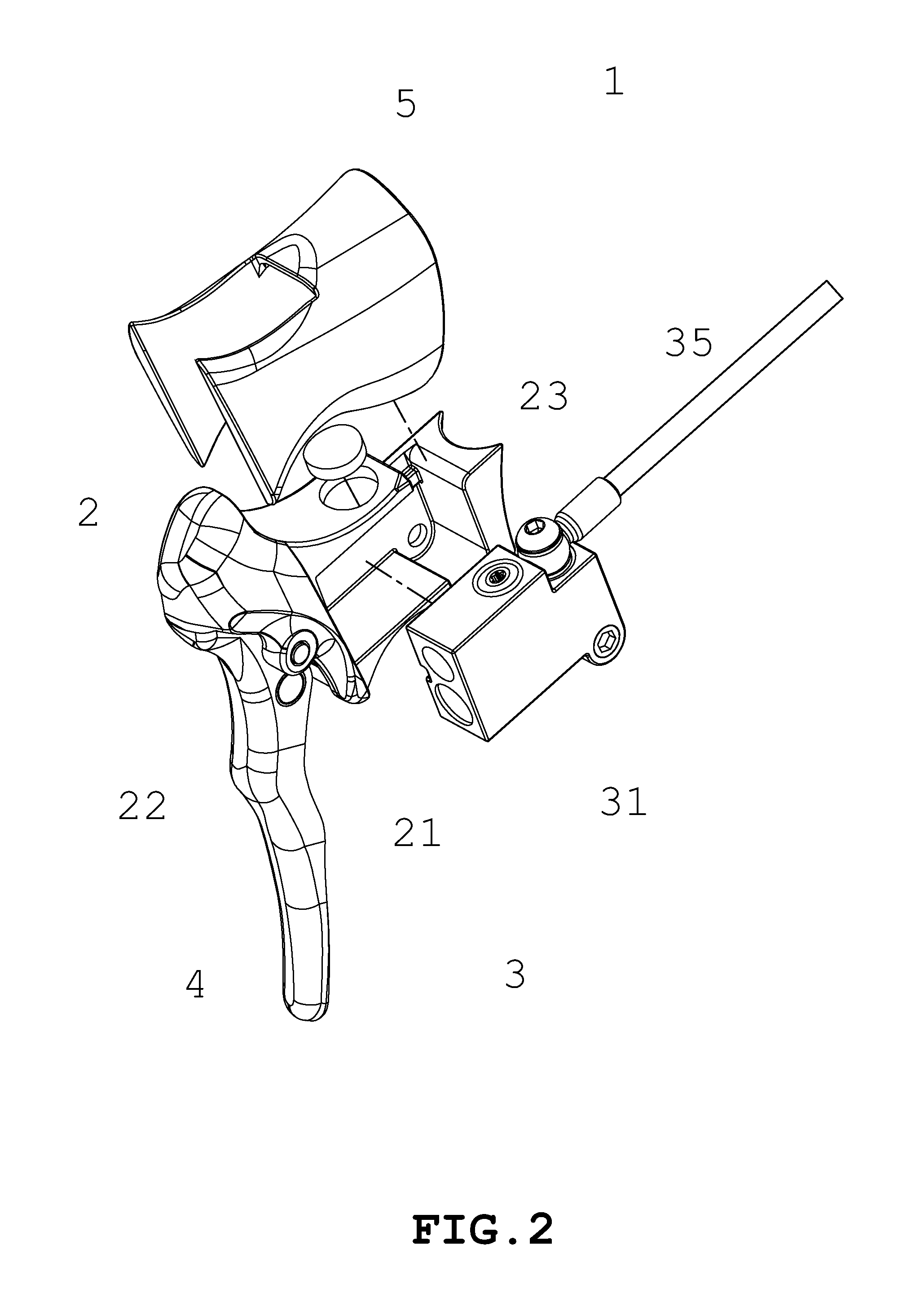
[0020]FIG. 1 is a perspective view of a braking device according to the invention. FIG. 2 is an exploded view of a braking device according to the invention. FIG. 3 is a perspective view of a braking device according to the invention. FIG. 4 is a schematic view of a part of a braking device applied onto a racing bicycle according to the invention.

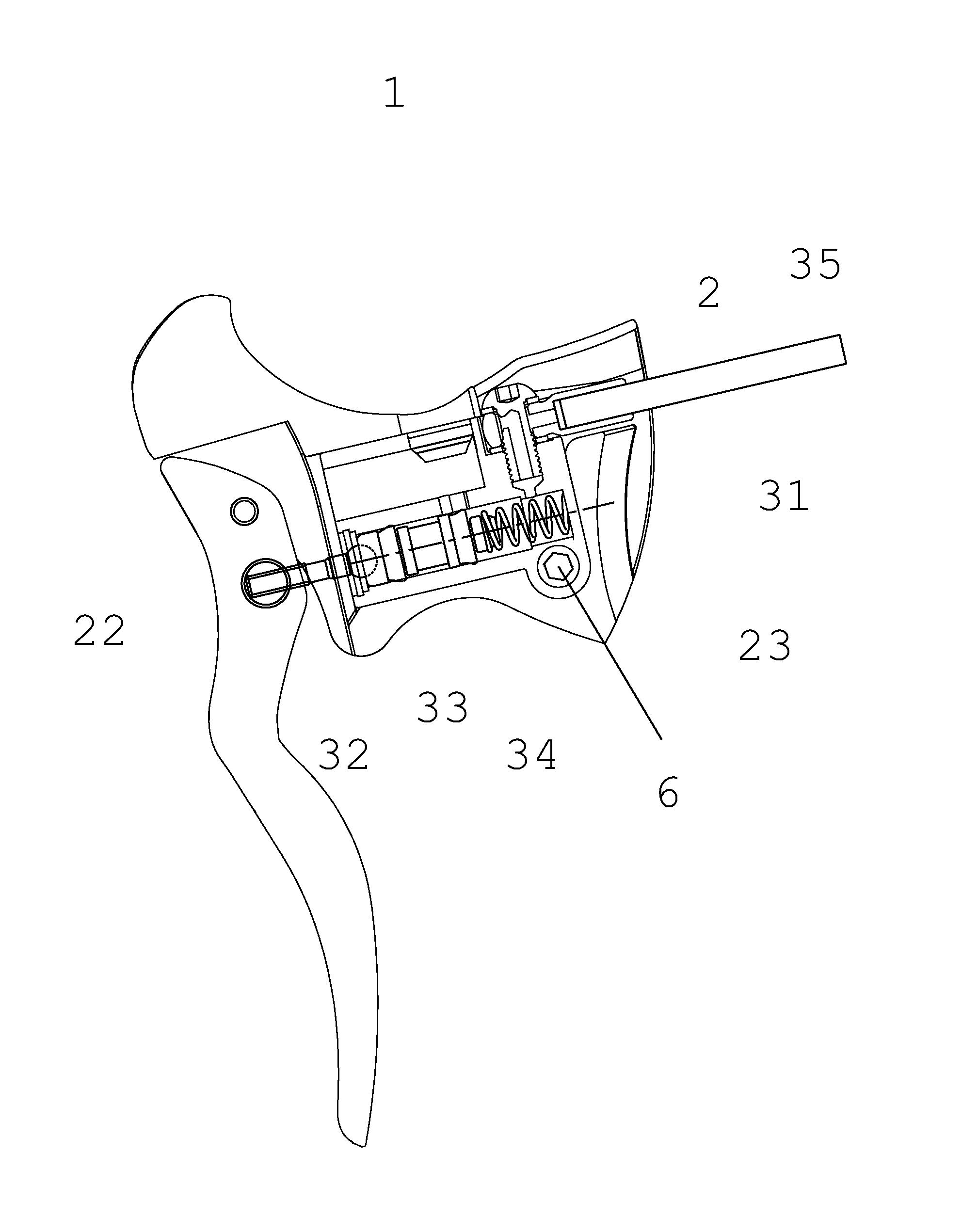
[0021]The braking device 1 of the invention includes a body 2, a hydraulic unit 3 and a handlebar 4.

[0022]The body 2 has an accommodating section 21, a pivoting terminal 22 and an open terminal 23. The handlebar 4 can be pivotally connected to the pivoting terminal 22.

[0023]The hydraulic unit 3 is hidden inside the accommodating section 21. The wa...


PUM


Abstract

A braking device with a hidden hydraulic cylinder has a hydraulic cylinder hidden inside a body of the braking device and further protected by a casing made of plastics, rubber or light alloy. Thereby, the space can be saved and any leakage due to unexpected collision. A tube is mounted to the hydraulic cylinder at any angle, preventing any wear or breaks due to frequent use. Therefore, the braking device of this invention is particularly suitable to the road bicycle.

Description

BACKGROUND OF THE INVENTION[0001]1. Field of the Invention[0002]The present invention relates to a braking device, particularly to a braking device with a hidden hydraulic cylinder for a road bicycle.[0003]2. Description of Related Art[0004]A conventional braking device for a bicycle is a brake hinged on a bicycle frame and reaches braking effect by clipping two brake pads on wheel rim.[0005]In order to meet the requirements for innovation and special purpose such as bicycle race, a conventional braking device has not satisfied for the user's demand of pursuing high-quality product. A disc break type brake has come to replace the conventional one.[0006]In order to control the disc brakes, a hydraulic cylinder is connected to a braking handlebar and a tube. Since the hydraulic cylinder must be mounted on an external surface of the bicycle, there causes inconvenience for the user in use and it is easy to cause leakage if any unexpected collision occurs. The tube is fixedly mounted in ...

Claims


Application Information

Patent Timeline
Patent Type & Authority Applications(United States)
IPC IPC(8): B62L3/02G05G1/04
CPCY10T74/20474B62L3/023
Inventor TSAI, SZU-FANG
Owner TEKTRO TECH
Why Eureka
Try Eureka