Segmented wind lock configuration for overhead roll-up doors and method of constructing the same

a wind lock and configuration technology, applied in the direction of door/window protective devices, curtain suspension devices, shutters/movable grilles, etc., can solve the problems of increasing the resistance of the side column, the side edge may become stuck or jammed, and the side edge may be known to be thickened continuously, so as to reduce friction and maintain the disengageability. , the effect of reducing the resistan

Active Publication Date: 2012-09-27
RYTEC CORP
View PDF6 Cites 12 Cited by
  • Summary
  • Abstract
  • Description
  • Claims
  • Application Information

AI Technical Summary

Benefits of technology

[0013]According to another aspect of the invention, at least two vertically spaced thickened edge wind locks capable of engaging a portion of a respective side column are attached proximate each marginal edge of the door panel. Providing the at least two spaced apart wind locks along each edge of the door panel increases the wind load resistance of the door panel as the door is opening and closing as the wind locks provide an increased thickness within the side columns, preventing disengagement of the door panel as a result of a wind load being applied to it, while providing substantial breakaway-ability if the door panel is impacted by an object as only portions of thickened edges rather than a continuous thickened edge must be pulled through the side columns.
[0014]According to another aspect of the invention, the wind locks may include a thickened body, an angled face facing the interior of the opening configured to engage a portion of the respective side column, and a substantially straight portion extending substantially perpendicular from a face of the door panel, the substantially straight portion being aligned with a lateral edge of the door panel. Angling an engaging face of the wind lock may help maintain substantial disengage-ability of the wind lock and door panel should the door or any of its components be impacted by an object.
[0015]According to a further aspect of the invention, the thickness of each wind lock and the vertical distance each wind lock extends along the face of the door panel may be adjusted to meet the wind load and breakaway characteristics of the door and door panel. Providing a thicker and / or longer wind lock increases the size and surface area of the wind lock, providing additional resistance to wind or air pressure against the door panel. In situations where less wind load resistance and more disengage-ability is required, as should be appreciated by those having skill in the art, either one or both of the thickness or vertical length of the wind lock may be reduced to reduce the surface area and amount of wind lock that must pass through the side column should the door or any of its components be impacted by an object.
[0017]According to still another aspect of the invention, the door assembly may further include a material covering at least a portion of the wind locks, and in some cases, at least a portion of the door panel along the marginal edge between each wind lock. Covering the wind locks and marginal edges of the door panel with a material having a lower resistance than the wind locks or door panel, like for example covering a rubber door panel and rubber or PVC wind lock with a fabric or a plastic material, may assist in reducing the friction between the wind locks and the side columns of the door panel to help maintain disengage-ability. Covering portions of the door panel and / or the wind locks with a friction reducing material also has the added benefit of protecting the door panel and / or wind locks from the forces of friction, reducing the amount of wear on the door panel and / or wind locks resulting from engagement with the side columns.
[0018]According to another aspect of the invention, a strip of material may be attached on the face of the door panel to which the wind locks are not attached, i.e. the face opposite the wind locks. As with covering at least portions of the wind locks and / or the door panel there between, placing a material like fabric or plastic over the opposite face of the door panel may reduce the friction between the side columns on the door panel, protecting the door panel from wear and maintaining disengage-ability, while at the same time increasing a total thickness of the door panel, thereby marginally increasing the wind load resistance of the same.

Problems solved by technology

However, there are at least three major drawbacks to using these known continuous thickened side edges.
For example, these overhead roll-up doors are typically installed in high-traffic areas with the potential to be impacted by objects or vehicles when the door is opening or closing.
While many of these doors include features which allow the door panel to disengage when impacted with such a force, when a continuous thickened edge is applied to the opposing side edges of the door panel the opposing edges may become stuck or jammed in the side columns.
If the continuous thickened edges become jammed in the side columns, the door panel may not be able to fully disengage from the side columns, increasing the likelihood of damage to the side columns, the door panel, the thickened edges, or other components associated with the door panel, like for example a bottom bar.
In addition, if these thickened side edges become stuck or jammed in the side column, the sticking or jamming may prevent the motor from raising the door panel, potentially damaging the motor and preventing any self-repair features of the door panel from working.
Another problem with the utilization of continuous wind locks is that they typically substantially increase the diameter of the door panel when it is substantially fully wound on the drum in a substantially open position.
The larger diameter requires a larger header which may be more costly and consequently may result in a smaller opening.
Still another drawback to using continuous thickened edges is that continuous thickened edges may increase the total weight of the door, creating additional stress on the motor controlling the door as it moves vertically.
However, these knobs or protrusions may offer less resistance than is necessary, and, under extreme forces, like for example high winds or forces imparted by objects impacting the door panel, thereby resulting in such knobs or protrusions breaking away from the door panel, eliminating any wind load resistance benefit they provide.

Method used


Image

  • Segmented wind lock configuration for overhead roll-up doors and method of constructing the same
  • Segmented wind lock configuration for overhead roll-up doors and method of constructing the same
  • Segmented wind lock configuration for overhead roll-up doors and method of constructing the same

Examples


Embodiment Construction

[0031]While the present invention is susceptible of embodiment in many different forms, there is shown in the drawings and will herein be described in detail, preferred embodiments of the invention with the understanding that the present disclosure is to be considered as an exemplification of the principles of the invention and is not intended to limit the broad aspect of the invention to the embodiments illustrated.

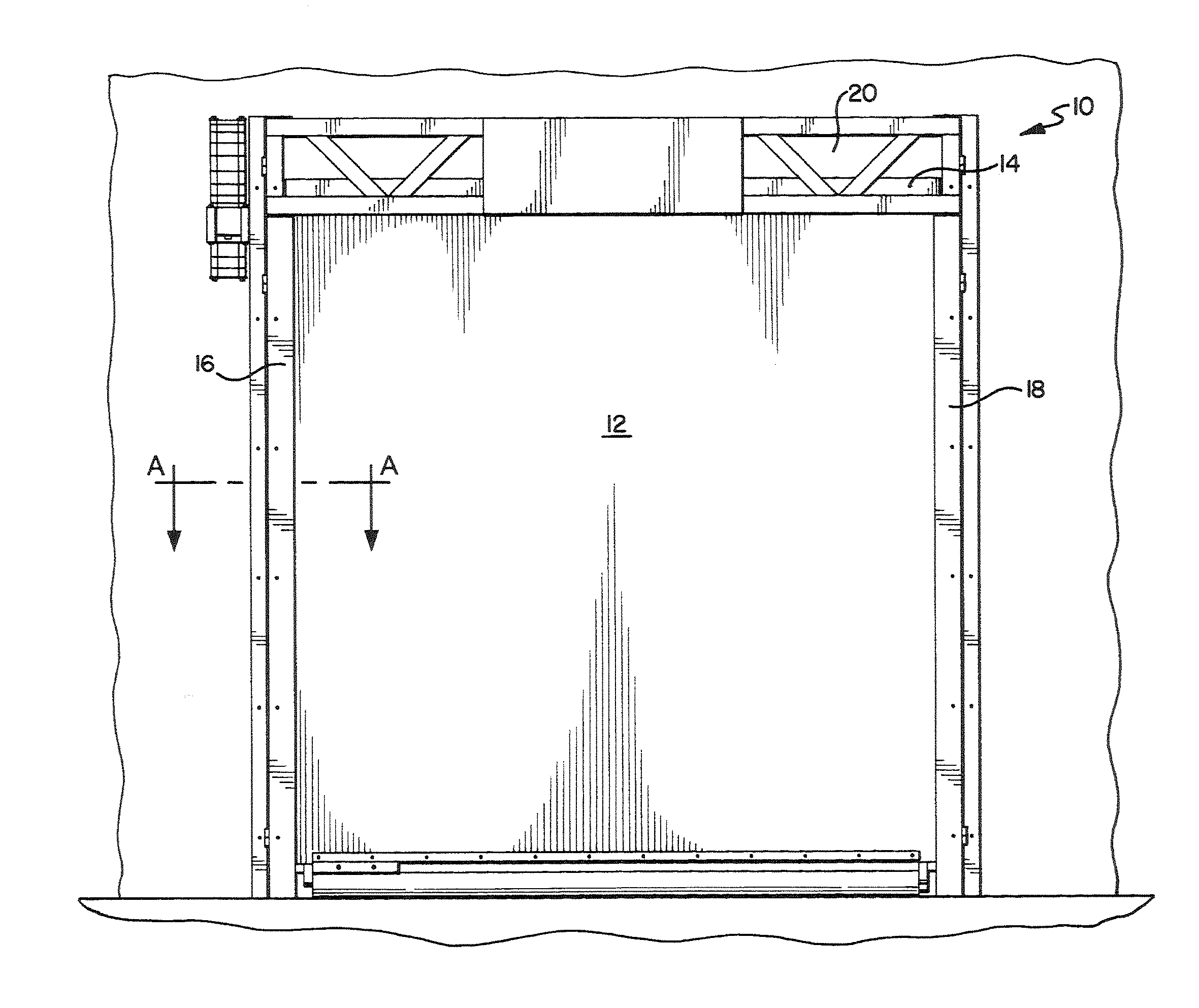
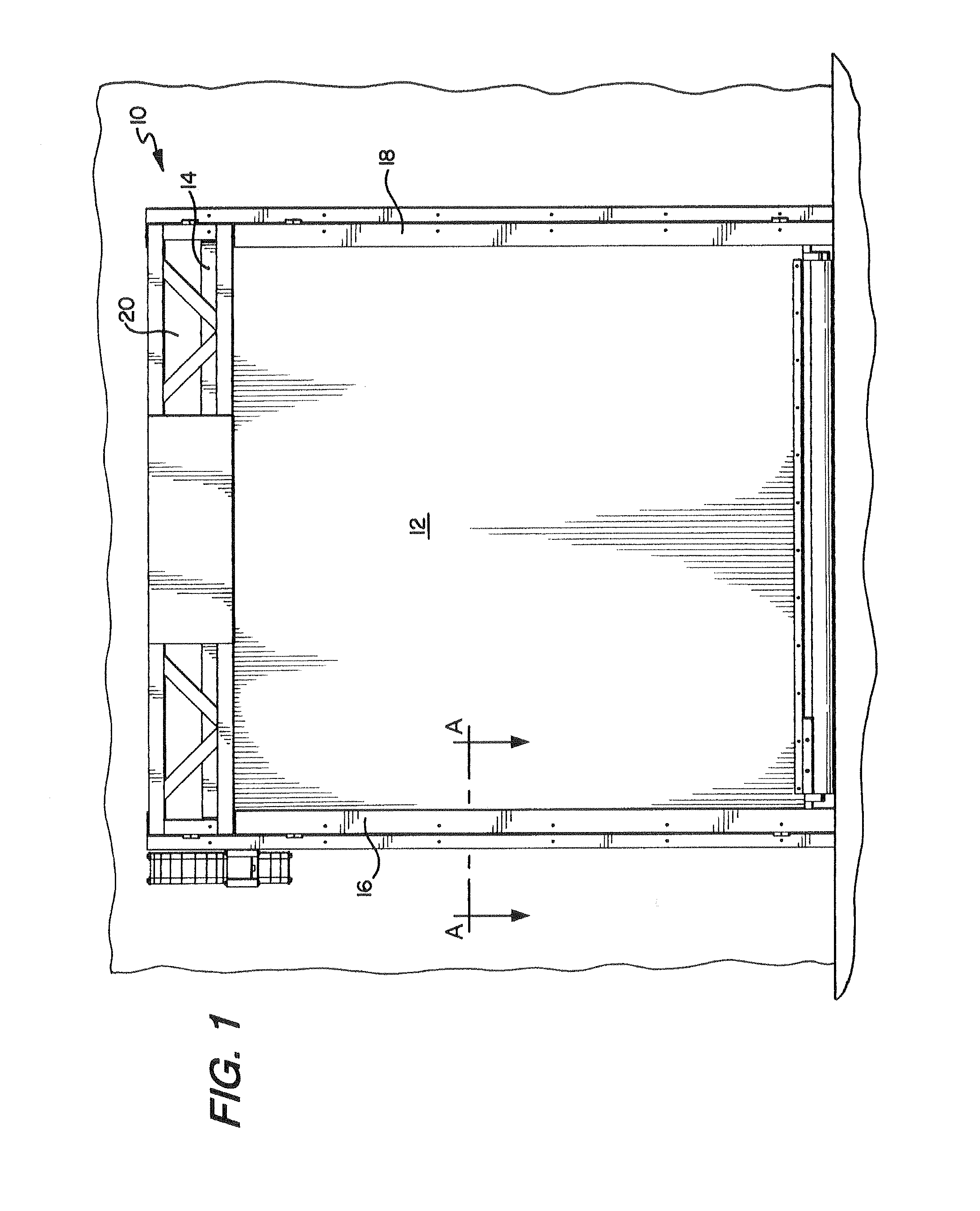
[0032]FIG. 1 shows a door assembly 10 having door panel 12, drum 14 for winding and unwinding door panel 12 to permit and prohibit access to an opening, side columns 16, 18 which engage a marginal edge of door panel 12 (and which further guide door panel 12 between the open and closed position) and header 20 for housing drum 14 and any unrolled portion of door panel 12.

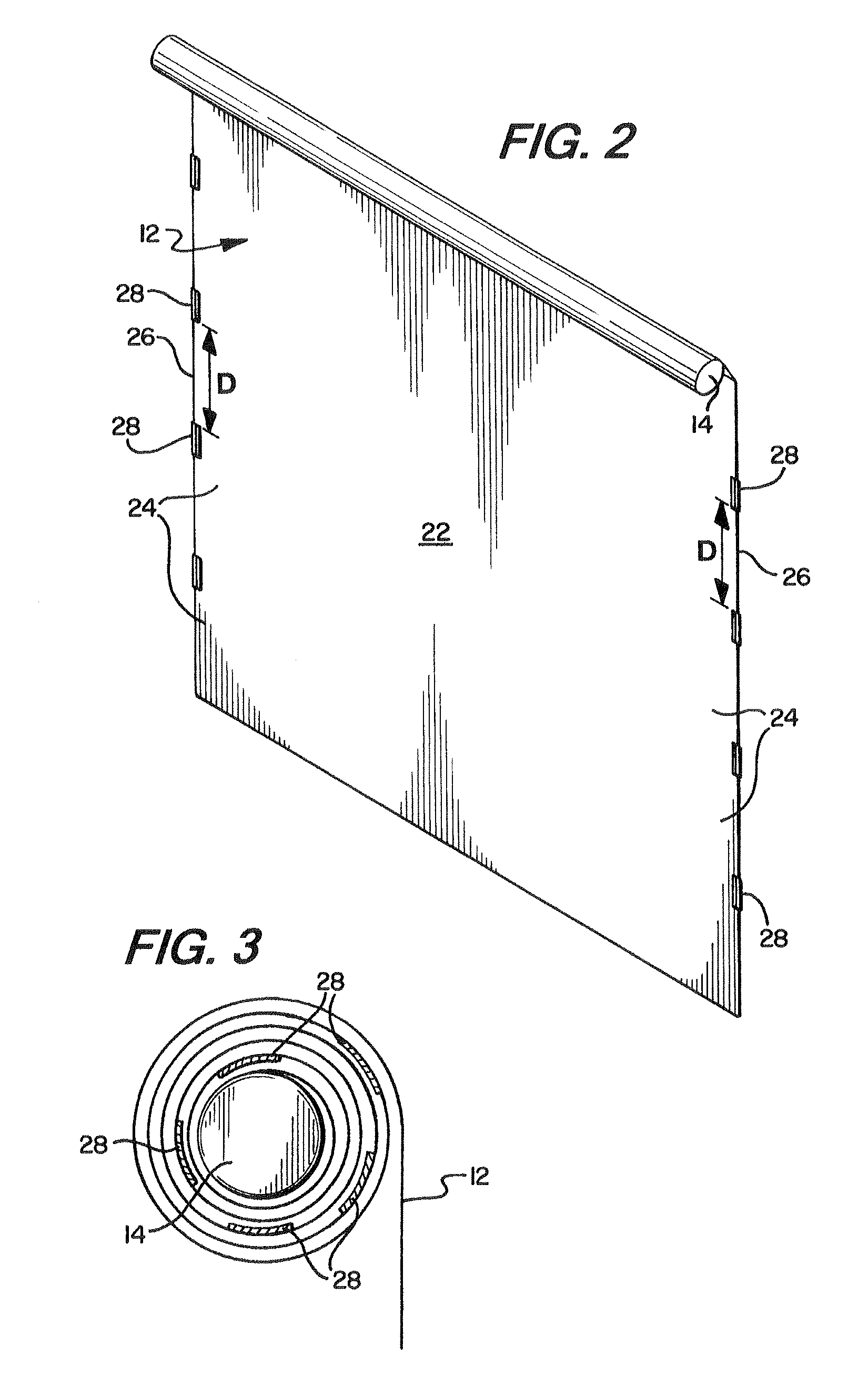
[0033]FIG. 2 shows an isolated view of door panel 12 and drum 14 as contemplated by an embodiment of the invention. As seen in FIG. 2, door panel 12 includes a first face 22, opposing marginal edges 24 and...


PUM

PropertyMeasurementUnit
heightaaaaaaaaaa
thicknessaaaaaaaaaa
speedaaaaaaaaaa

Abstract

An overhead roll-up door assembly for a vertically moving door to permit and prohibit access to an opening, the door assembly having a door panel with two faces and opposing marginal and lateral edges, and at least two wind locks attached proximate each marginal edge. The at least two wind locks extend away from one face of the door panel in a direction substantially perpendicular thereto, and are spaced apart vertically along each respective side edge of the door panel. The assembly further includes a drum for winding and unwinding the door panel to permit and prohibit access to the opening, and, a pair of opposing parallel side columns aligned and spaced apart such that each of the opposing side edges engage one of the side columns in a manner in which at least a portion of the side columns guide vertical movement of the door panel.

Description

RELATED APPLICATIONS[0001]This application claims priority to U.S. Provisional Application Ser. No. 61 / 466,922 entitled “Segmented Wind Lock Configuration For Overhead Roll-Up Doors And Method Of Using Same” filed Mar. 23, 2011; and, U.S. Provisional Application Ser. No. 61 / 534,356 entitled “Continuous Wind Lock Configuration For Overhead Roll-Up Door” filed Sep. 13, 2011—the contents of both of which are fully incorporated herein by reference.FIELD OF THE INVENTION[0002]The present invention is related to overhead roll-up doors, and more specifically to a door panel for any overhead roll-up door having a segmented wind lock for preventing the door panel from disengaging with the door assembly from the force of wind.BACKGROUND OF THE INVENTION[0003]Overhead roll-up doors provide resistance to high winds and / or air pressure. These doors typically include a door panel having opposing side edges that engage with, and are vertically guided in, side columns. In order to enhance the door'...

Claims


Application Information

Patent Timeline
Patent Type & Authority Applications(United States)
IPC IPC(8): E06B3/44B23P11/00
CPCE06B9/13E06B9/58E06B2009/585Y10T29/49826E06B5/12E06B9/68E06B3/44E06B9/581
Inventor DRIFKA, BRIAN NORBERTGONTARSKI, CHRISTOPHER
Owner RYTEC CORP
Why Eureka
Try Eureka