Sensor device and measurement method

a technology of a sensor device and a measurement method, which is applied in the direction of resistance/reactance/impedence, instruments, chemical indicators, etc., can solve the problems of not being able to know the state of the reinforcing bars in the concrete structure nor of the concrete, and therefore being unable to know the state of the reinforcing bars. to achieve the effect of accurate detection

Active Publication Date: 2012-09-27
SEIKO EPSON CORP
View PDF22 Cites 10 Cited by
  • Summary
  • Abstract
  • Description
  • Claims
  • Application Information

AI Technical Summary

Benefits of technology

[0041]According to such a measurement method, the difference in electric potential between the first electrode and the second electrode has sharp changes which depend on the presence or absence of the passivation film, which is associated with the changes in pH o

Problems solved by technology

However, in a concrete structure that is affected after construction by acid rain, exhaust gas, and the like, the concrete will be gradually acidified, and the reinforcing bars will therefore corrode.
However, in the sensor device according to the above mentioned publication, between the time when the fine wires first begin to corrode and the time when a fine wire is disconnected, it is not possible to know the state of the reinforcing bars in the concrete structure nor of the concrete (more specifically, it is not possible to know, for example, the pH, or the concentration of chloride ions).
Further, the re

Method used


Image

  • Sensor device and measurement method
  • Sensor device and measurement method
  • Sensor device and measurement method

Examples


first embodiment

[0057]Firstly, the first embodiment of the present invention shall now be described.

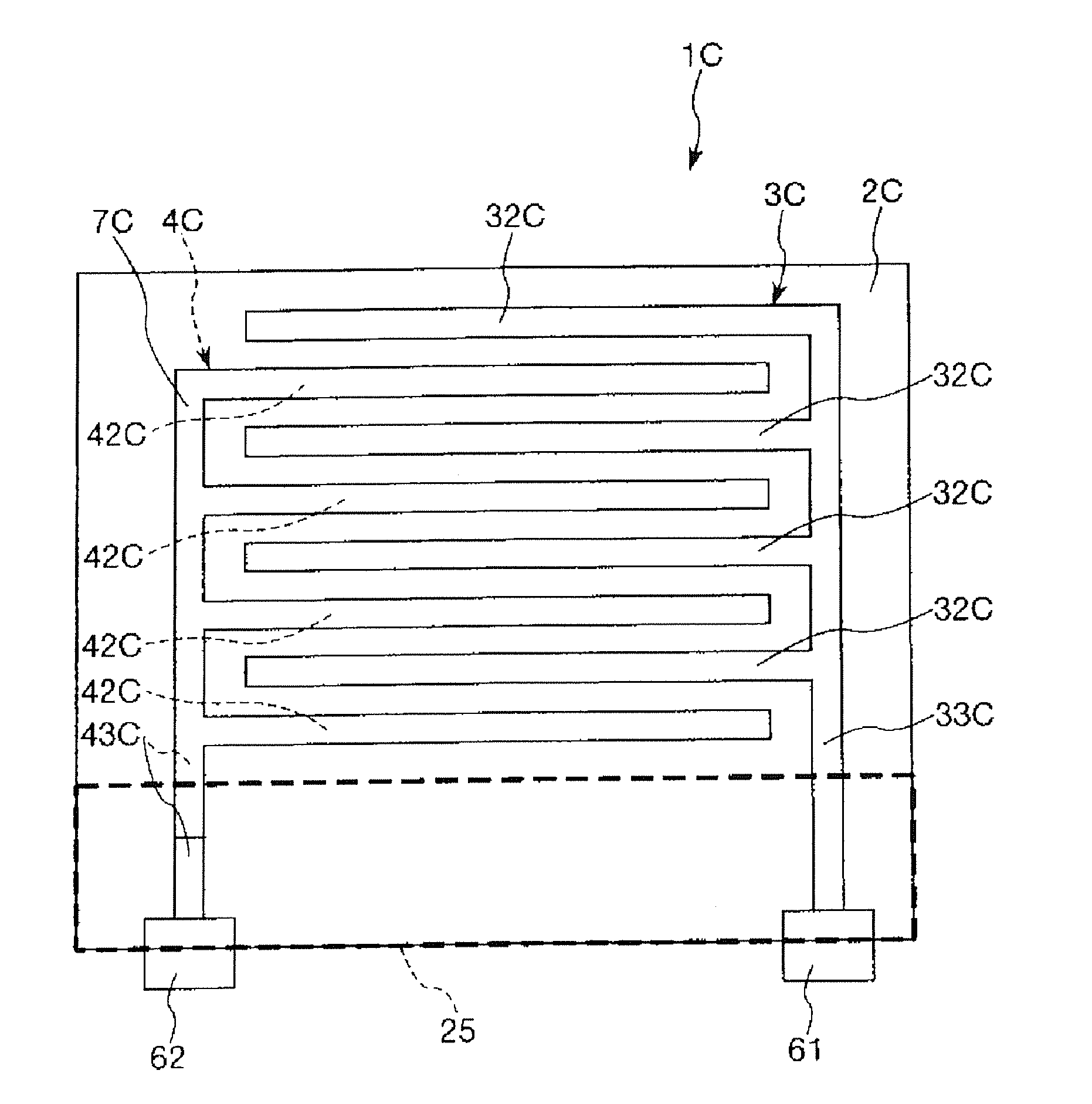
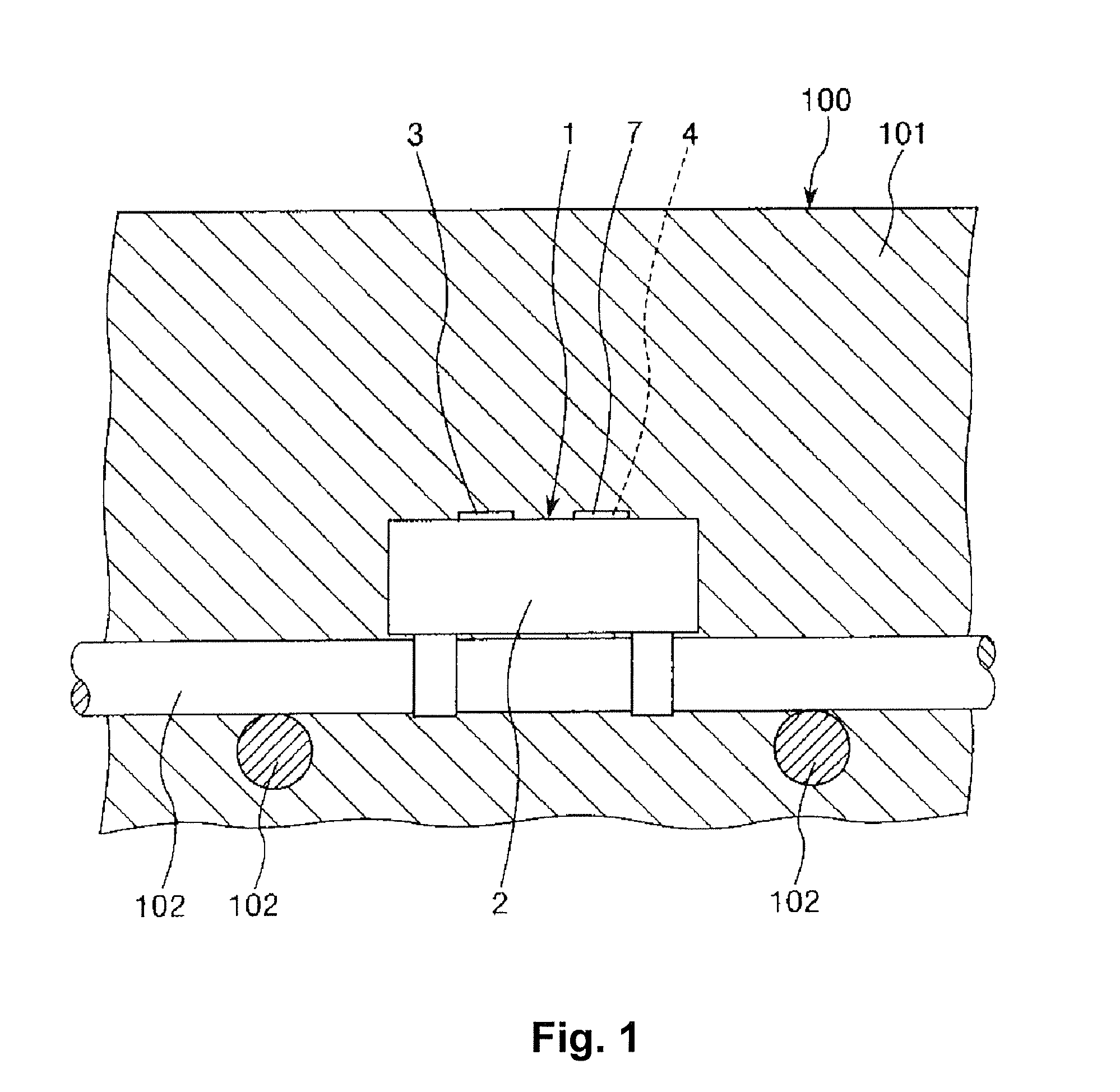
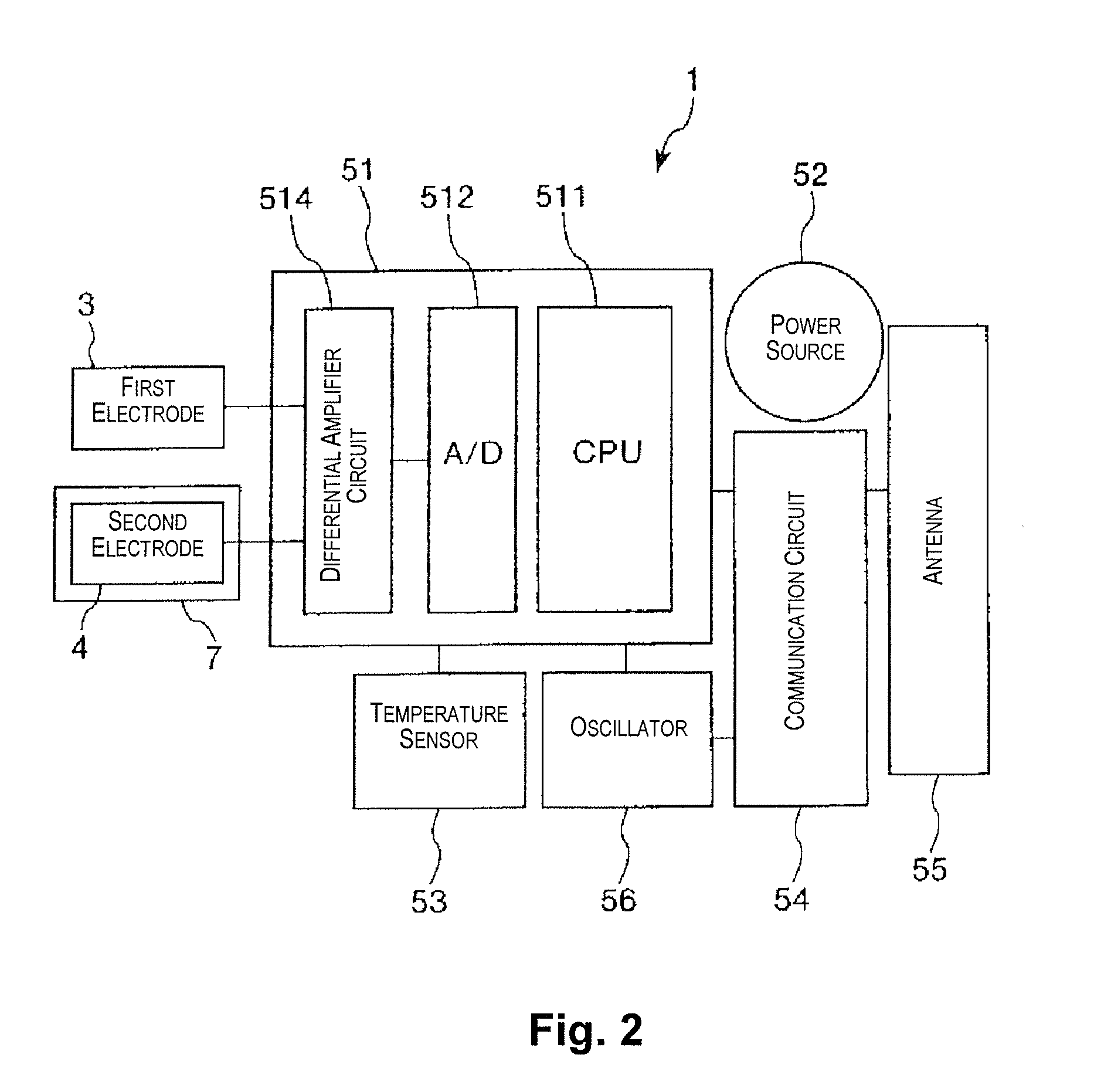
[0058]FIG. 1 is a drawing illustrating an example of the state of use of a sensor device according to a first embodiment of the present invention. FIG. 2 is block diagram illustrating a schematic configuration of the sensor device illustrated in FIG. 1. FIG. 3 is a plan view for describing a first electrode, a second electrode, and a functional element illustrated in FIG. 2. FIG. 4 is a cross-sectional view (a cross-sectional view along the A-A line in FIG. 3) for describing the first electrode and the second electrode illustrated in FIG. 2. FIG. 5 is a cross-sectional view (a cross-sectional view along the B-B line in FIG. 3) for describing the functional element illustrated in FIG. 2. FIG. 6 is a circuit diagram illustrating a differential amplifier circuit provided to the functional element illustrated in FIG. 2. FIG. 7 is a drawing illustrating an example of the manner in which the pH and electri...

second embodiment

[0135]The following is a description of a second embodiment of the present invention.

[0136]FIG. 9 is a drawing illustrating an example of the state of use of a sensor device according to the second embodiment of the present invention.

[0137]The following description of the second embodiment focuses on the points of difference with the embodiment described above, and omits a description of any similar matters.

[0138]The sensor device of the second embodiment is substantially similar to the sensor device of the first embodiment, except in that the number and shapes in plan view of the first electrode and the second electrode are different. Constituent elements which are similar to the embodiment described above have been assigned like reference numerals.

[0139]A sensor device 1A of this embodiment has: a main body 2A; a plurality of first electrodes 3A1, 3A2, 3A3 and a plurality of second electrodes 4A1, 4A2, 4A3 exposed on the surface of the main body 2A; and coating films 7A1, 7A2, 7A3...

third embodiment

[0148]The following is a description of a third embodiment of the present invention.

[0149]FIG. 10 is a cross-sectional view for describing a first electrode and a second electrode of a sensor device according to the third embodiment of the present invention.

[0150]The following description of the third embodiment focuses on the points of difference with the embodiments described above, and omits a description of any similar matters.

[0151]The sensor device of the third embodiment is substantially similar to the sensor device of the first embodiment, except in that both the first electrode and the second electrode are covered by the coating film. Constituent elements which are similar to the embodiments described above have been assigned like reference numerals.

[0152]A sensor device 1B of this embodiment has a first coating film 71 for covering a first electrode 3, and a second coating film 72 for covering a second electrode 4.

[0153]The first coating film 71 and the second coating film...


PUM


Abstract

A sensor device includes first and second electrodes, a coating film and a functional element. The first electrode includes a first metallic material in which either a first passivation film forms on a surface thereof or the first passivation film present on the surface thereof is lost, in association with changes in the pH of a measurement site. The second electrode includes a second metallic material different from the first metallic material, and is spaced apart from the first electrode. The coating film includes a third metallic material different from the first and second metallic materials. The coating film covers at least the first or second electrode. The functional element is configured to measure a difference in electric potential between the first and second electrodes that changes depending on presence or absence of each of the first passivation film and the coating film in association with the changes in pH.

Description

CROSS-REFERENCE TO RELATED APPLICATIONS[0001]This application claims priority to Japanese Patent Application No. 2011-062764 filed on Mar. 22, 2011. The entire disclosure of Japanese Patent Application No. 2011-062764 is hereby incorporated herein by reference.BACKGROUND[0002]1. Technical Field[0003]The present invention relates to a sensor device, and to a measurement method.[0004]2. Related Art[0005]There are known sensor devices which, for example, measure the state of corrosion of a reinforcing bar in concrete (e.g., Japanese Laid-Open Patent Publication No. 11-153568).[0006]Typically, the concrete in a concrete structure immediately after construction exhibits a strong alkalinity. For this reason, the reinforcing bars in a concrete structure immediately after construction have a passivation film formed on the surface thereof and are therefore safe. However, in a concrete structure that is affected after construction by acid rain, exhaust gas, and the like, the concrete will be ...

Claims


Application Information

Patent Timeline
IPC IPC(8): G01N27/04
CPCG01N27/125G01N17/02G01N33/20G01N33/383G01N27/4167G01N31/221
Inventor KATO, JURIMIYAZAWA, TAKAO
Owner SEIKO EPSON CORP
Why Eureka
Try Eureka