Relative Touch User Interface Enhancements

a user interface and relative touch technology, applied in instruments, cathode-ray tube indicators, computing, etc., can solve the problems of inability to use single input device or input paradigm, inability to navigate the spatial selection paradigm of the gui, and difficulty in remembering keyboard shortcuts, etc., to improve the use of the human finger, improve the presentation of the underlying on-screen content, and improve the effect of the user experien

Active Publication Date: 2012-09-27
INTELLITACT
View PDF11 Cites 116 Cited by
  • Summary
  • Abstract
  • Description
  • Claims
  • Application Information

AI Technical Summary

Benefits of technology

[0011]It is a further objective to provide the user with visual aids and other tools which enable the brain to make a strong correspondence between hand/finger motions and resulting computer operations, in order to minimize or eliminate the need for the user to constantly shift manual and visual focus. To achieve these and other objectives, some embodiments provide a multi-device UI that comprises at least two UIs, wherein a first UI is touch enabled and the first UI displays at least a subset of the second UI. The first UI may be presented using a touchscreen tablet, touchscreen smartphone, or other touch sensitive display on an essentially horizontal plane that is synchronously coupled with the second UI that may be presented using a monitor or display device that may be placed farther from the user on an essentially vertical plane. Synchronously coupling the first UI to the second UI allows touch inputs issued

Problems solved by technology

In so doing however, the OS and/or GUI has mutated in a way such that no single input device or input paradigm is singularly suited to fully interact with the OS and/or GUI because each input device has its own set of advantages and disadvantages.
The keyboard is efficient for use in performing text entry, but inefficient for use in navigating the spatial selection paradigm of the GUI.
While keyboard “shortcuts” which utilize “flag keys (e.g., option, control, command, alt, etc.) provide access to certain elements of a GUI, such keyboard shortcuts are often difficult to remember, inconsistent across different applications, and to invoke a keyboard shortcut, the user must often perform awkward hand movements and finger extensions in order to reach flag keys that are used in combination

Method used


Image

  • Relative Touch User Interface Enhancements
  • Relative Touch User Interface Enhancements
  • Relative Touch User Interface Enhancements

Examples


Embodiment Construction

[0066]I. Meta Touch Interface

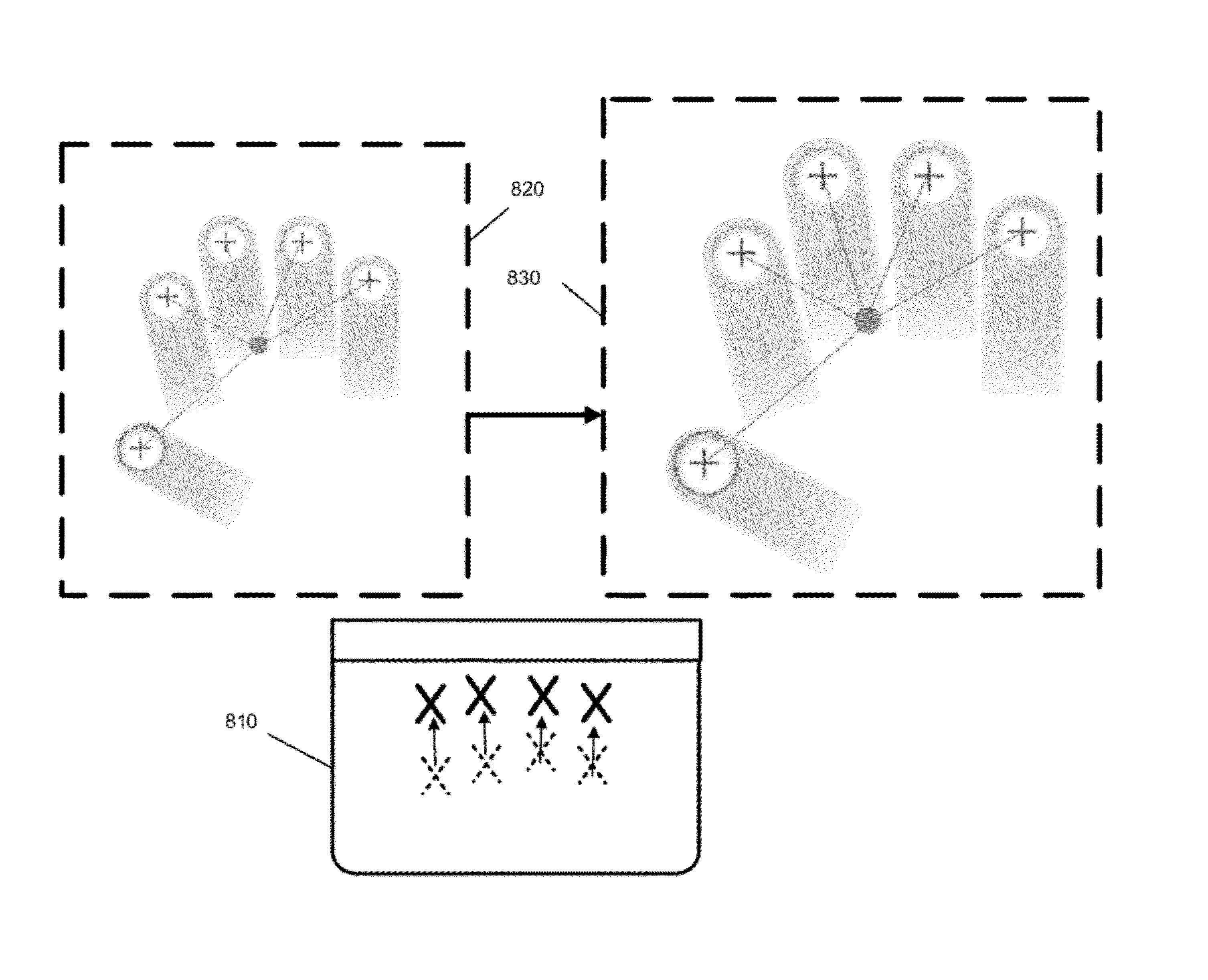
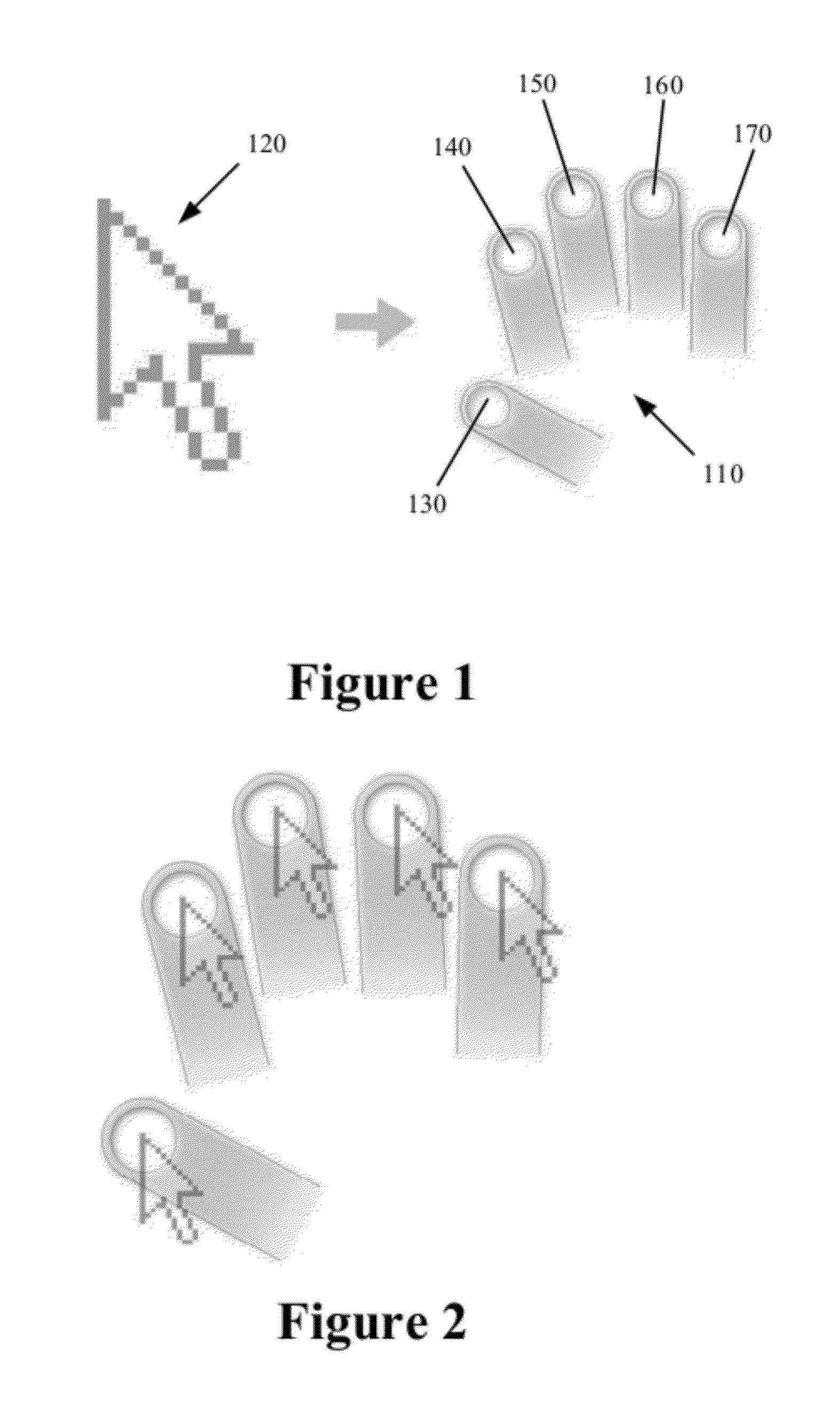
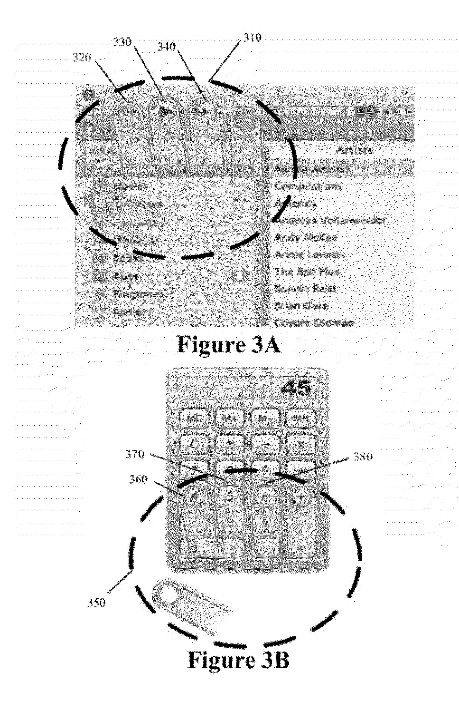
[0067]To address the previously discussed limitations associated with various computer input devices, it is an objective of the present invention to define an apparatus, method, system, and computer software product that integrates functionality from pointer based UIs, direct touch UIs, and discrete input UIs to enhance traditional GUI pointing tool interactions. It is further an objective of the present invention to define an apparatus, method, system, and computer software product that permits and encourages the device user to retain visual focus on the display device(s) on a vertical plane at eye level and manual touch on the input device(s) on a horizontal plane at hand level. To do so, some embodiments provide a meta touch interface (MTI) which simulates a screen-mapped direct-touch UI by allowing physical control to be performed on one or more separate, more conveniently situated surfaces, with analogous movements represented in context on-screen b...


PUM


Abstract

Some embodiments provide a meta touch interface (MTI) with multiple position indicators with each position indicator operating as a separate pointing tool that can be activated (i) using taps on a touchpad or other touch sensitive surface or (ii) by pressing certain keyboard keys. The MT pointer allows for adjacent UI elements to be selected without having to reposition the MT pointer for each selection or activation. Some embodiments provide a multi-device UI that comprises at least two UIs, wherein the first UI is presented on an essentially horizontal plane that is aligned with operational focus and the second UI that is presented on an essentially vertical plane that is aligned with visual focus of the user. Some embodiments provide a precision pointer that includes an adjustable magnified region to better present underlying on-screen content, thereby allowing the user to more precisely position the pointer.

Description

CLAIM OF BENEFIT TO RELATED APPLICATIONS[0001]This application claims the benefit of U.S. provisional application 61 / 493,523, entitled “Enhanced Pointer Tools for Graphical User Interfaces”, filed Jun. 6, 2011, is a continuation-in-part of U.S. non-provisional patent application Ser. No. 13 / 423,270 entitled “Input Device User Interface Enhancements” filed on Mar. 18, 2012 which claims the benefit of U.S. provisional application 61 / 465,345, entitled “Input Device User Interface Enhancements” filed Mar. 17, 2011, and is a continuation-in-part of U.S. non-provisional patent application Ser. No. 13 / 423,212 entitled “Touch Enhanced Interface” filed Mar. 17, 2012 which claims the benefit of U.S. provisional application 61 / 465,309, entitled “Touch Enhanced Interface”, filed Mar. 17, 2011. The contents of provisional applications 61 / 493,523, 61 / 465,345, and 61 / 465,309 and non-provisional application Ser. Nos. 13 / 423,270 and 13 / 423,212 are hereby incorporated by reference.TECHNICAL FIELD[000...

Claims


Application Information

Patent Timeline
IPC IPC(8): G06F3/041G06F3/02
CPCG06F3/04812G06F3/04883G06F2203/04104G06F3/04895G06F3/04886G06F3/0213G06F3/03547G06F3/0482G06F3/04842
Inventor LAUBACH, KEVIN
Owner INTELLITACT
Why Eureka
Try Eureka