Three phase inverter driver

a technology of inverter driver and three-phase inverter, which is applied in the direction of capacitors, battery/fuel cell control arrangements, propulsion by batteries/cells, etc., can solve the problems of prohibitively high cost and difficulty in converting energy storage output forms, and achieve the effect of reducing or eliminating the drop in the maximum voltage and reducing the maximum voltag

Inactive Publication Date: 2015-06-23
ENGIE STORAGE SERVICES NA LLC
View PDF2 Cites 1 Cited by
  • Summary
  • Abstract
  • Description
  • Claims
  • Application Information

AI Technical Summary

Benefits of technology

[0006]Typical embodiments of the invention are directed toward a three phase inverter driver and power conversion system wherein three single-phase inverters (1) have input ports connected to a common DC source or bus connected thereto and (2) have output ports each driving one of the three phases of a three-phase signal. In some embodiments, the output of the single-phase inverters or EVSE passes through a rectifying means, which may be internal to the EVSE. In some embodiments the single-phase inverters have modified-sine AC output which includes short intervals of zero output voltage when changing output polarity simultaneously. In other embodiments their outputs are staggered, either due to slight variance in their operation, manufacturing tolerances, or by intentional timing staggering, to minimize or eliminate the chance that all three phases of the three-phase output of the inverters are changing polarity simultaneously. In some other embodiments, there is an inexpensive, long-lasting capacitor installed in the system to mitigate the drop in the maximum voltage of the three-phase signal during any brief intervals where all three of the inverters transition polarity concurrently. In embodiments where the single-phase inverters' timing is staggered, the AC outputs of the three inverters may be synchronized, then staggered by approximately 120 degrees (or one third of a period) to prevent simultaneous polarity crossing.

Problems solved by technology

It is challenging to convert the energy storage output form into the required input form for the EVSE.
Some existing “all-in-one” three-phase inverters can perform this conversion, but they are prohibitively expensive.

Method used


Image

  • Three phase inverter driver
  • Three phase inverter driver
  • Three phase inverter driver

Examples


Embodiment Construction

[0015]Typical embodiments of the invention are directed toward a three phase inverter driver and power conversion system. Preferred embodiments of the system described herein may serve to improve the availability, accessibility, cost effectiveness, implementation, and operation of three-phase power converters and inverters, especially in the use of EVSE and fixed DC power sources.

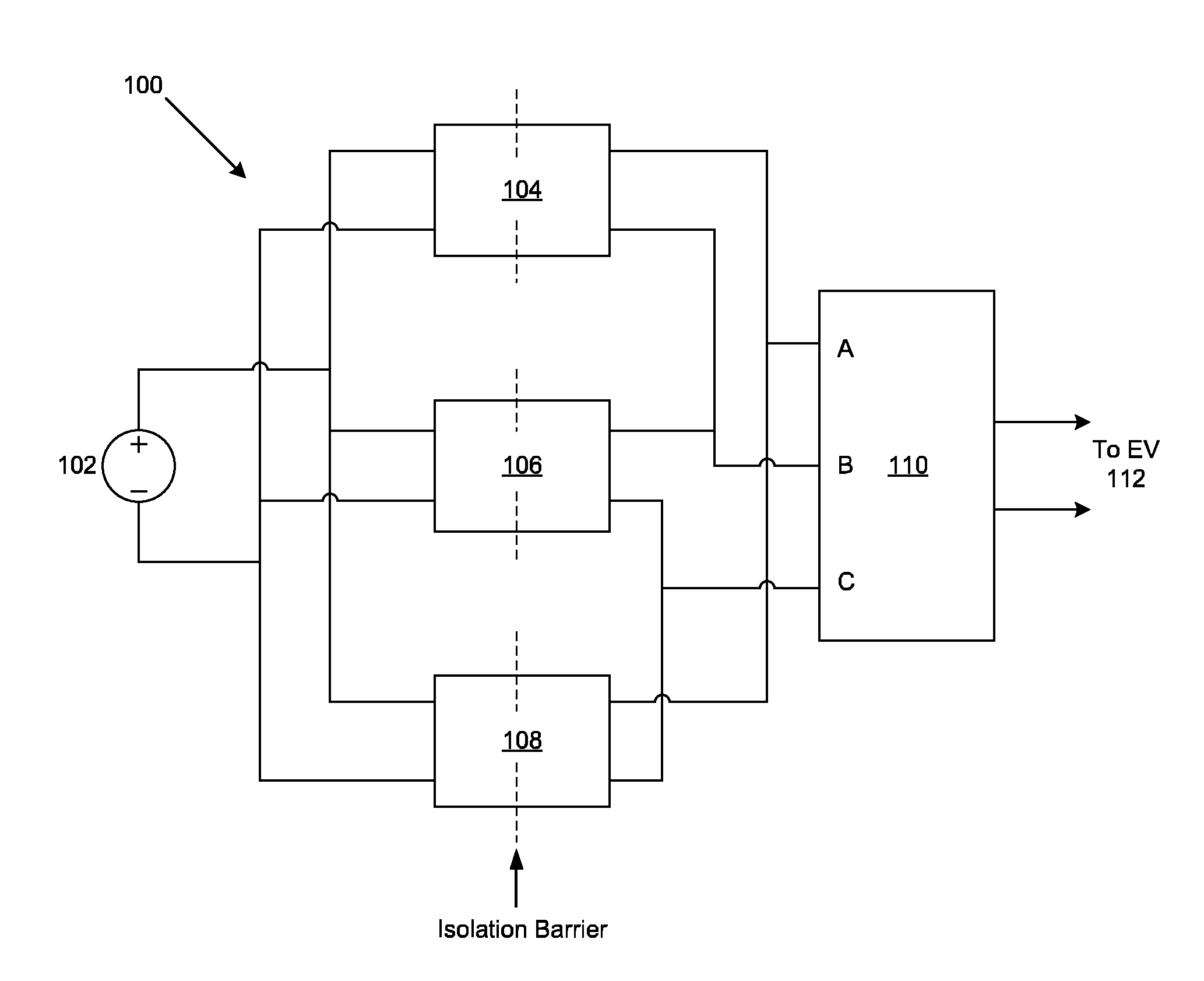
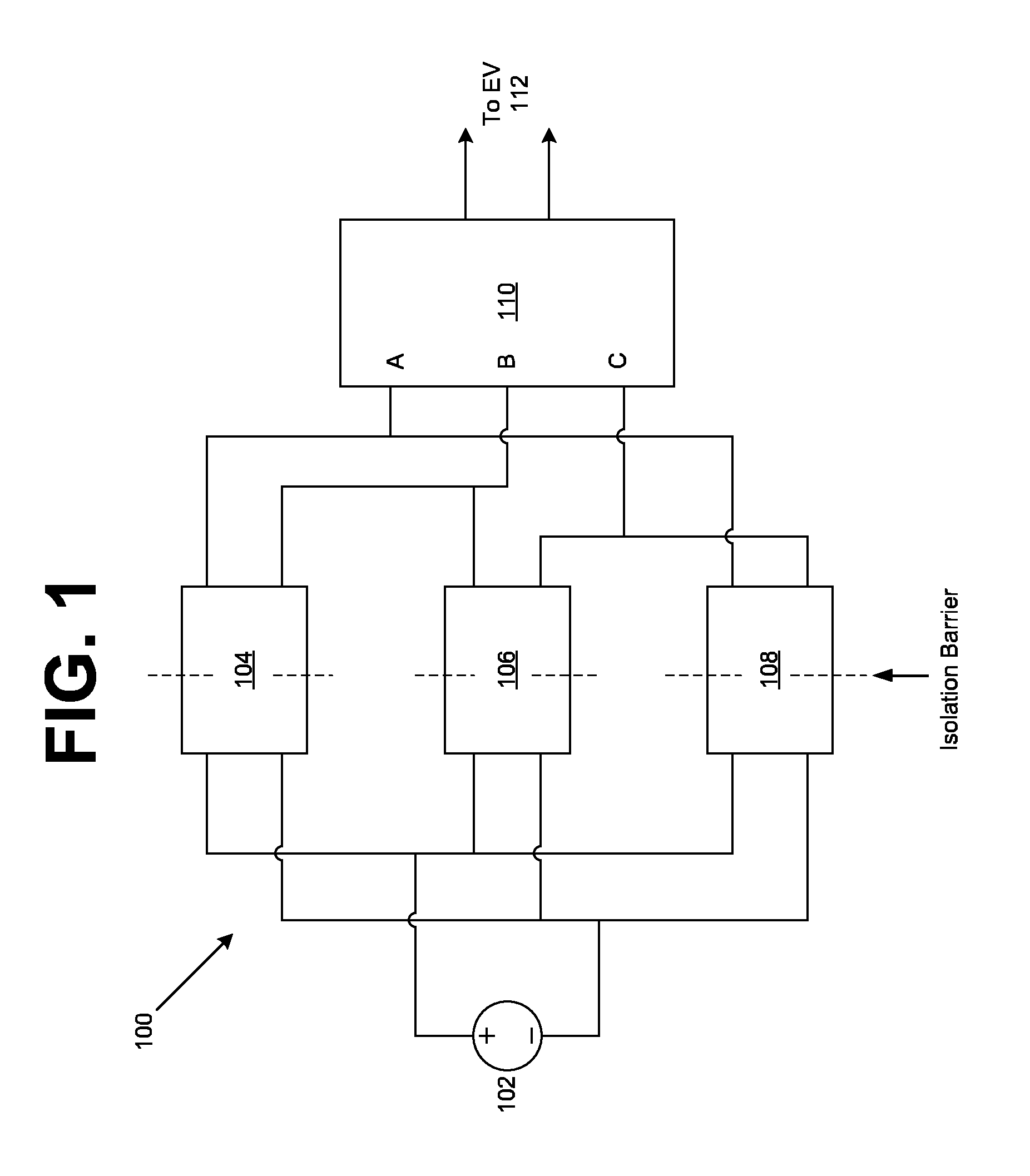
[0016]FIG. 1 is a circuit diagram of an exemplary three phase inverter driver system. The conversion system 100 is comprised of an energy source 102 that is connected to three single-phase inverters 104, 106, and 108 that provide three phase inputs A, B, and C of the EVSE 110. The EVSE 110 output is connected to the EV 112 or another connected energy storage device such as a battery bank on a mobile EV charging system. The three single-phase inverters 104, 106, and 108 are connected to the energy source 102 in parallel in order to symmetrically provide energy to each of them.

[0017]The energy source 102 show...


PUM


Abstract

A system and method of use of a three-phase inverter driver includes three single-phase inverters that are connected to the three-phase AC input of electric vehicle supply equipment (EVSE) so that each of the single-phase inverters provide one of the three phases of the AC signal used by the EVSE. The single-phase inverters are rectified and either have variance in their output frequencies or have their phases staggered so that the maximum voltage provided to the EVSE remains at a consistently high level. In some cases, the three phases each cross polarity simultaneously, resulting in a drop in the maximum three-phase voltage, so low-capacity capacitors are used in conjunction with the inverters to bridge these gaps in voltage. These systems and methods use readily available, inexpensive components that have regulatory safety-approval and therefore may allow implementation on a vehicle or with a load leveling energy storage system.

Description

CROSS-REFERENCE TO RELATED APPLICATIONS[0001]Not applicable.BACKGROUND[0002]The present invention is directed to the fields of power converters, inverters, electric vehicle charging equipment, and related fields.[0003]Due to the rising popularity of electric vehicles (EVs) on the market today, demand for high power electrical grid connections has greatly increased due to a need for high power EV charging stations. Desirable charging rates of high capacity electric vehicle batteries require high power levels that are not available from typical household electrical systems. As such, electrical connections that can provide high voltage AC or DC “Level 2” or “Level 3” Electric Vehicle Service Equipment (EVSE) are important to the growth of the electric vehicle service industry.[0004]In some cases, an EVSE may rely on batteries to provide the energy needed for EV charging. This is especially useful in applications where the EV is charged by a mobile or portable energy storage device or i...

Claims


Application Information

Patent Timeline
Patent Type & Authority Patents(United States)
IPC IPC(8): H02J1/00H02M7/30H02M7/00H02J7/00H02J3/00B60L1/00B60L11/00B60L11/18H02M1/12
CPCH02J7/0065H02M7/30H02M7/00B60L1/00H02M1/12H02J3/00B60L1/006B60L11/1812B60L11/185B60L11/1881B60L11/005B60L11/1803Y10T307/707Y02T10/7241Y02T90/14B60L2210/44B60L2240/527B60L2210/20Y02T10/7022Y02T10/725Y02T90/34Y02T90/128Y02T90/127Y02T90/121Y02T10/7072B60L53/22B60L50/40B60L50/51B60L53/11B60L58/30Y02T10/70Y02T10/72Y02T90/40H02J2207/20Y02T90/12
Inventor TADDEO, STEPHEN R.
Owner ENGIE STORAGE SERVICES NA LLC
Why Eureka
Try Eureka