Method For Determining A Video Capture Interval For A Calibration Process In A Multi-Projector Display System

a multi-projector display and calibration process technology, applied in the field of multi-projector display systems, can solve the problems of large-scale display that is no longer constrained by commodity projectors, cannot achieve very high resolution, project over vast areas, or create bright projections on very bright surface areas

Inactive Publication Date: 2012-09-27
SEIKO EPSON CORP
View PDF10 Cites 14 Cited by
  • Summary
  • Abstract
  • Description
  • Claims
  • Application Information

AI Technical Summary

Problems solved by technology

Until recently, large screen displays were typically too costly, physically unwieldy, or simply unavailable.
No longer do commodity projectors remain constrained to dimly lit rooms with well prepared display surfaces.
Even with these improvements, however, it is still difficult or impossible for a single commodity projector to achieve very high resolutions, project over vast areas, or create bright projections on very bright surface areas (for example, near day lit windows).
Unfortunately, construction of such large displays is complex and costly.
One common technique, such as grouping multiple projectors together and tiling their projection output to produce large screen displays of any desired size, presents challenging problems with registration (that is, alignment of projector pixels).
Color and luminosity variance across separate devices and even within a given device is difficult to correct.
Minor shape or geometric inconsistencies of the display surface can also hinder adequate results.
Projector lumens, or light output, may not be adequate for brighter locations.
Synchronizing content delivery to the individual components forming the larger display are additional hurdles to solve.
Some of these problems apply to single-projector displays as well.
If the output pixels from one projector are not close enough to those from another projector, a visible gap may occur between the projections on the composite display.
Likewise, overlapping pixels across projectors produce bright seams that are also objectionable.
High-end projectors with specialized lens optics or edge blending/blurring filters may be available to reduce some of these problems, but are far from optimal.
Specialized projectors and mounting hardware, measurement tools, and tedious calibration methods are additional requirements that add to the resource costs and complexities of physical projector alignment which can become too demanding for the average user.
In many configurations, physical alignment may even be impossible using projectors with limited optic pathways,

Method used


Image

  • Method For Determining A Video Capture Interval For A Calibration Process In A Multi-Projector Display System
  • Method For Determining A Video Capture Interval For A Calibration Process In A Multi-Projector Display System
  • Method For Determining A Video Capture Interval For A Calibration Process In A Multi-Projector Display System

Examples


Embodiment Construction

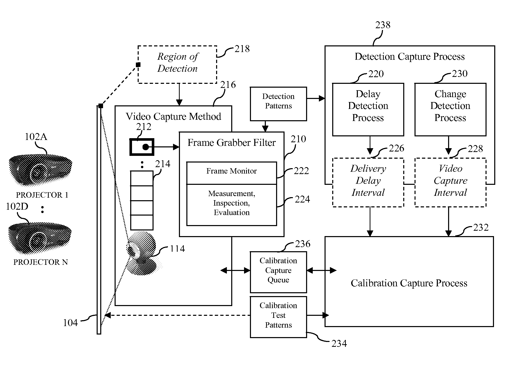
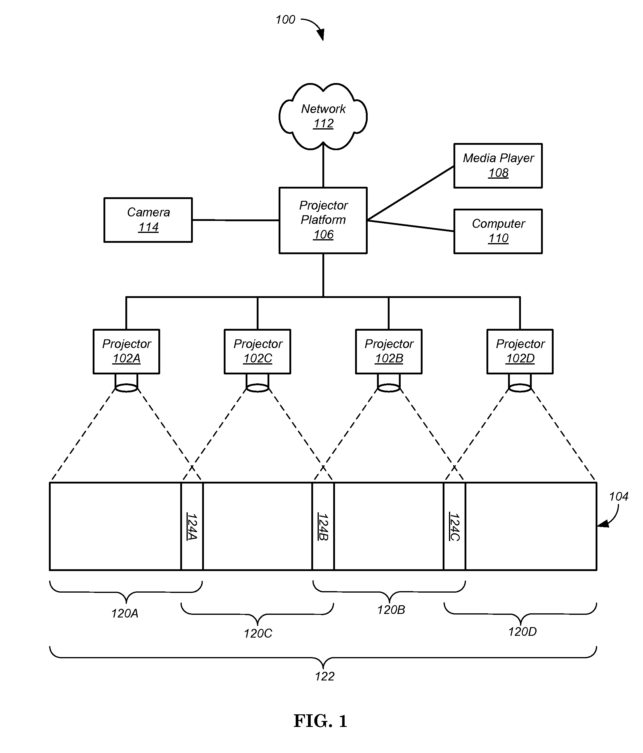
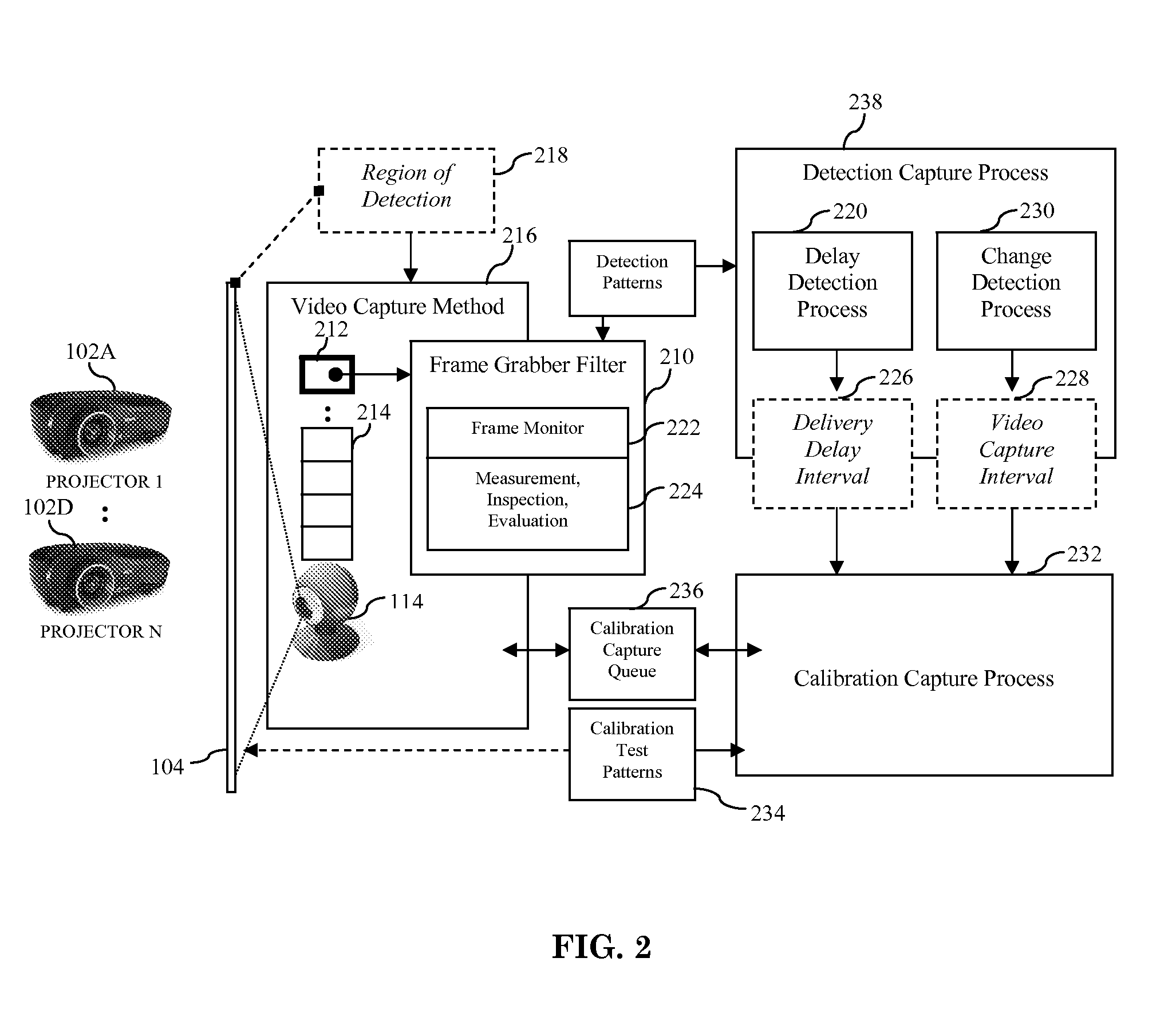
[0028]The present invention relates to camera-based registration of projector display systems. During registration, one or more projectors project calibration images upon a display surface. A camera captures one or more images of each projected calibration image. A projector platform creates a mapping, for each projector, between pixel locations of the camera and pixel locations of the projector. After registration, the mappings are used to alter the images prior to projection so that seamless composite image can be displayed by the multiple projectors.

[0029]These mappings are stored in Virtual Pixel Map (VPM) files that form an accurate pixel registration map of each projector. Using the VPM files, each physical device pixel on a projector can be mapped to one or more logical pixels in a virtual region defining the large format display (composite image). This virtual large format display resolution defines the unit of each VPM pixel, which is a virtual pixel in the logical display ...


PUM


Abstract

First, a delivery delay, i.e. the time it takes for a content to be captured and a representative frame made available (i.e. delivered), is determined. Second, a video capture interval, i.e. a minimum time delay requirement between stable captured content frames, is determined. In other words, the recycle time-period after which it is safe to change frame content during a capture interval without impacting a prior stable video frame in the pre-delivery stage is determined.

Description

CROSS-REFERENCE TO RELATED APPLICATIONS[0001]This application is related to commonly owned U.S. patent application Ser. No. 12 / 728,838, filed Mar. 22, 2010, and Ser. No. 12 / 549,011, filed Aug. 27, 2009, which are hereby incorporated by reference in their entirety.FIELD OF INVENTION[0002]The present invention relates generally to multi-projector display systems. More particularly, the present invention relates to accurate calibration of the system during registration of each of the multiple projectors.BACKGROUND[0003]With an ever growing desire to see more information with better quality, large-screen displays have become quite popular. Increasing screen resolutions and sizes are continually emerging and made available in televisions, computer monitors, and other video devices. Until recently, large screen displays were typically too costly, physically unwieldy, or simply unavailable. Video projectors provided one solution, enabling a wide range of communication and entertainment fun...

Claims


Application Information

Patent Timeline
IPC IPC(8): H04N3/26
CPCH04N9/3147H04N17/00H04N9/3194H04N9/3179
Inventor IVASHIN, VICTOR
Owner SEIKO EPSON CORP
Why Eureka
Try Eureka