Nonsymmetric optical system and design method for nonsymmetric optical system

a design method and optical system technology, applied in the field of optical systems, can solve the problems of limited thompson's theory and few practical forms

Active Publication Date: 2012-09-27
UNIVERSITY OF ROCHESTER
View PDF10 Cites 15 Cited by
  • Summary
  • Abstract
  • Description
  • Claims
  • Application Information

AI Technical Summary

Benefits of technology

[0038]further comprising designing the imaging optical system characterized by an overall RMS wave front error less than λ / 100 at 10 μm over the full field of view.

Problems solved by technology

While there are special configurations that eliminate axial coma, there are very few practical forms that do not reduce to a rotational symmetric form.
However, due to the fact that any tilted and decentered optical system with rotationally symmetric parent surfaces could not be corrected for axial coma, this theory has previously only been useful during the optical design of offset aperture and / or field biased optical systems.
The theory developed by Thompson is limited to tilted and decentered optical imaging systems made up of rotationally symmetric components, or offset aperture portions thereof.

Method used


Image

  • Nonsymmetric optical system and design method for nonsymmetric optical system
  • Nonsymmetric optical system and design method for nonsymmetric optical system
  • Nonsymmetric optical system and design method for nonsymmetric optical system

Examples


Embodiment Construction

[0053]Reference will now be made in detail to the present exemplary embodiments of the invention, examples of which are illustrated in the accompanying drawings.

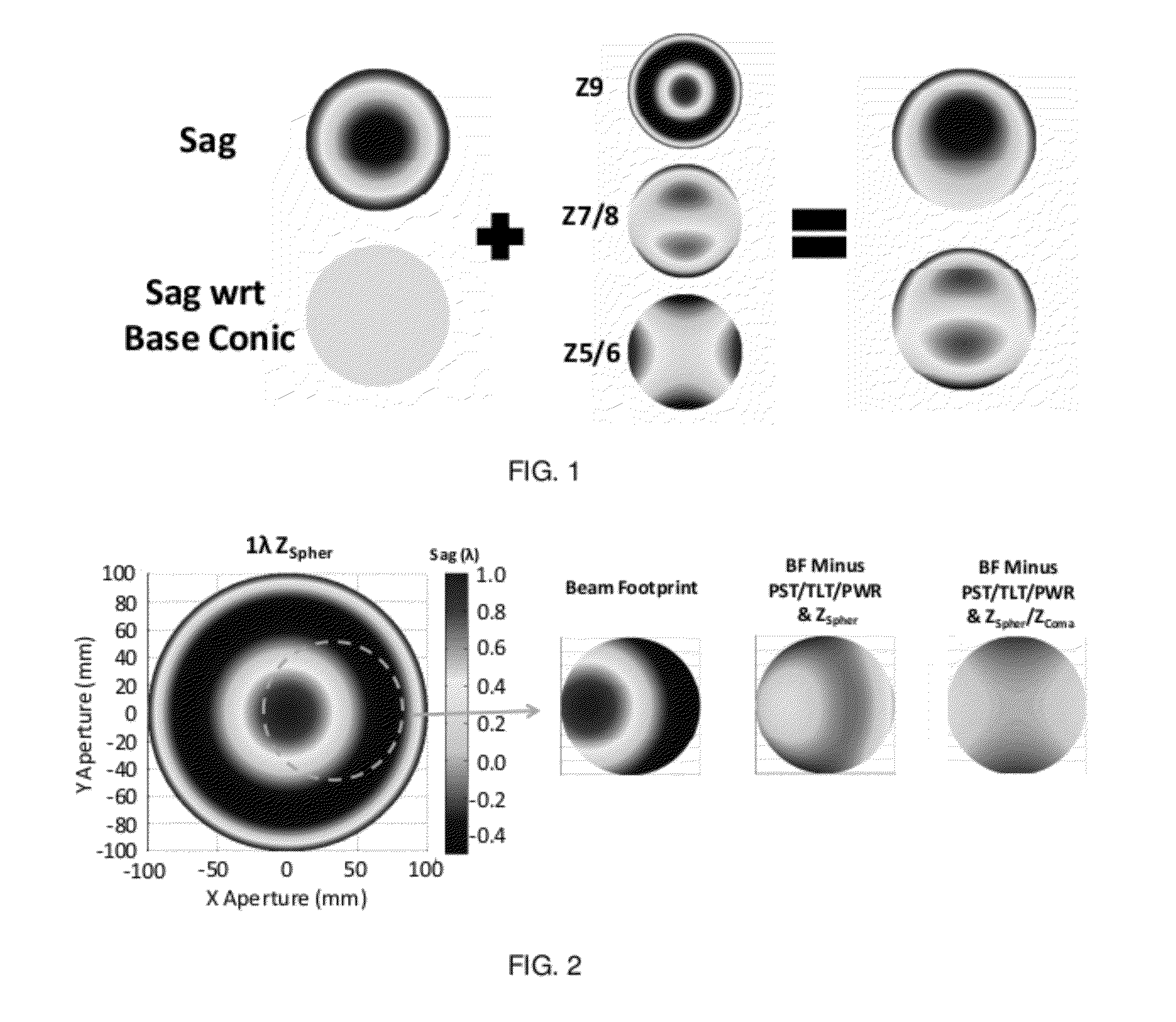
[0054]A φ-polynomial surface takes the form,

z=F(ρ,φ),   (1)

where the sag, z, is represented by a function that depends on the radial component, ρ, and the azimuthal component, φ, within the aperture of the part. Until recently, methods of fabrication have constrained the shape of optical surfaces to depend on the radial component only, that is, z=F(ρ). This limitation has been a severe constraint in the optical design of unobscured optical systems. It is well known that when any powered optical surface in an optical system is tilted or decentered with respect to the optical axis, third-order coma will appear on-axis. While there are some special configurations where axial coma is eliminated (1:1 systems and systems that use the coma free pivot design principle), in general, the ubiquitous presence of axial coma in tilted and...


PUM


Abstract

A new family of truly nonsymmetric optical systems that exploit a new fabrication degree of freedom enabled by the introduction of slow-servos to diamond machining; surfaces whose departure from a sphere varies both radially and azimuthally in the aperture, and associated design method.

Description

RELATED APPLICATION DATA [0001]The instant application claims priority to U.S. Provisional application Ser. No. 61 / 546,230 filed on Oct. 12, 2011 and U.S. Provisional application Ser. No. 61 / 467,075 filed on Mar. 24, 2011, the subject matters of which are incorporated herein by reference in their entireties.GOVERNMENT FUNDING [0002]This invention was made with support from the National Science Foundation under Agreement No. ECCS-1002179. The government has certain rights in the invention.BACKGROUND [0003]1. Field of the Invention[0004]Embodiments of the invention are generally directed to the field of optical systems; particularly to nonsymmetric imaging optical systems and, more particularly to nonsymmetric imaging optical systems having two or more phi (φ)-polynomial surfaces, and methods for designing such nonsymmetric optical systems.[0005]2. Related Art Discussion[0006]Starting in the 1960s, motivated by the advance in LWIR detectors and the accompanying need for stray light co...

Claims


Application Information

Patent Timeline
Patent Type & Authority Applications(United States)
IPC IPC(8): G02B17/06
CPCG01M11/025G01M11/005
Inventor ROLLAND, JANNICK P.FUERSCHBACH, KYLE
Owner UNIVERSITY OF ROCHESTER
Why Eureka
Try Eureka