
Dual Carrier Modulation

a dual-carrier, modulation technology, applied in the field of coding units, can solve problems such as complex decoding of modulated signals

Inactive Publication Date: 2012-09-27
CAMBRIDGE SILICON RADIO
View PDF3 Cites 2 Cited by
  • Summary
  • Abstract
  • Description
  • Claims
  • Application Information

AI Technical Summary

Problems solved by technology

However, a constellation of 256 points has a very high dynamic, so that more bits are needed for the analogue-to-digital converter, and it is complex to decode the modulated signal because it is necessary to distinguish between the 256 points in the constellation.

Method used


Image

  • Dual Carrier Modulation
  • Dual Carrier Modulation
  • Dual Carrier Modulation

Examples


Embodiment Construction

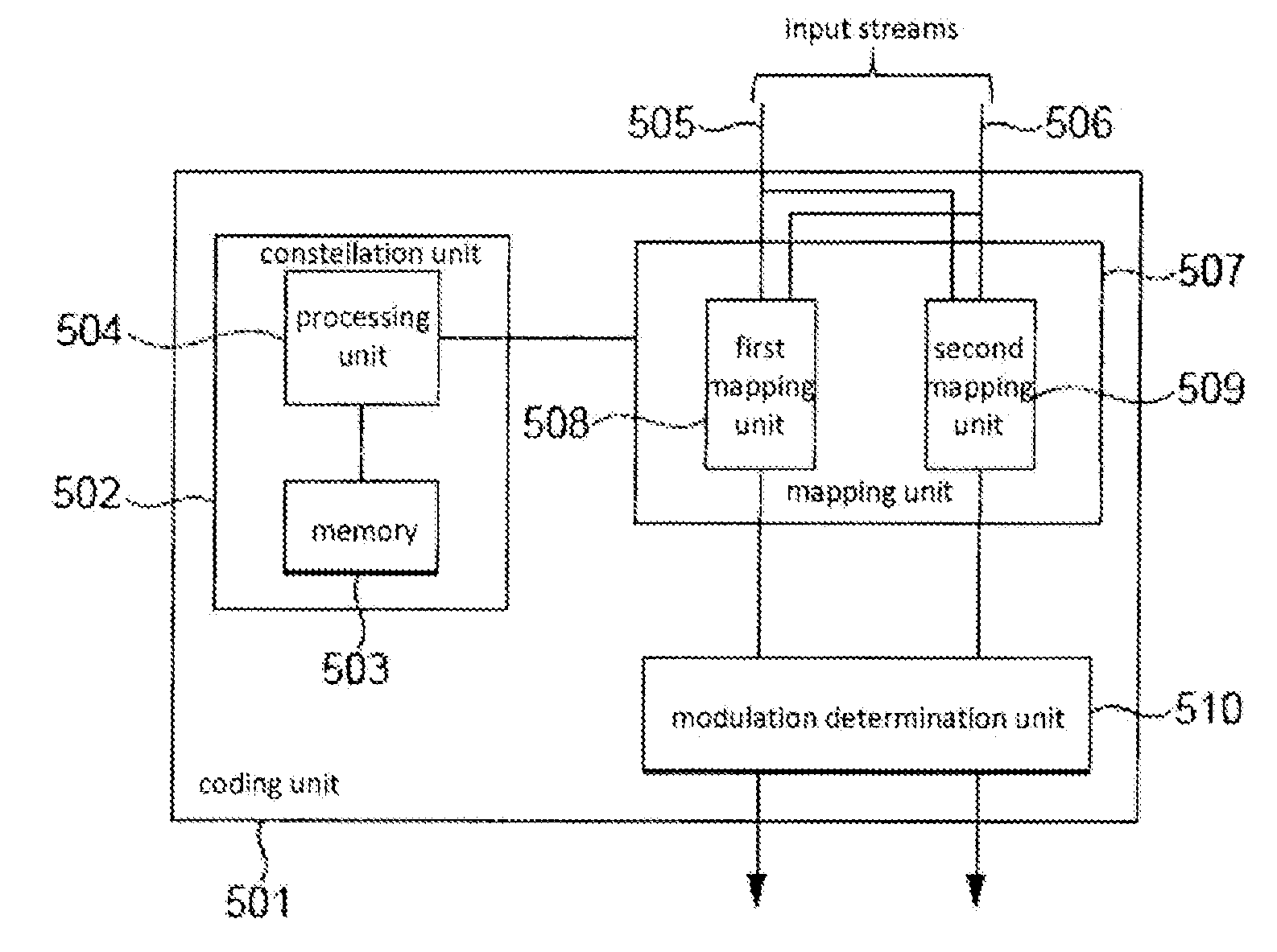
[0071]A coding unit may be arranged to determine the amplitude and phase modulations that should be applied to the two carrier signals of a DCM scheme. The coding unit may be arranged to first determine a group of modulation points that represent the different amplitude / phase modulation combinations that may be applied to the carrier signals. The coding unit may then be arranged to associate a data symbol to be transmitted by the carrier signals with two of the modulation points. This may be achieved by using a first mapping function to map the data symbol onto a first modulation point and a second mapping function to map the data symbol onto a second modulation point. The first and second modulation points each carry all of the information associated with one data symbol, together with some or all of the information associated with another data symbol. The coding unit may then be arranged to determine that the amplitude and phase modulation associated with the first modulation poin...


PUM


Abstract

An encoder arranged to encode a data symbol for transmission by means of two carrier signals in accordance with an encoding scheme having the properties that: for a first carrier signal, a plurality of data symbols are mapped to a single modulation point in a constellation of modulation points; and for a second carrier signal, said plurality of data symbols are each mapped to a different modulation point in the constellation of modulation points.

Description

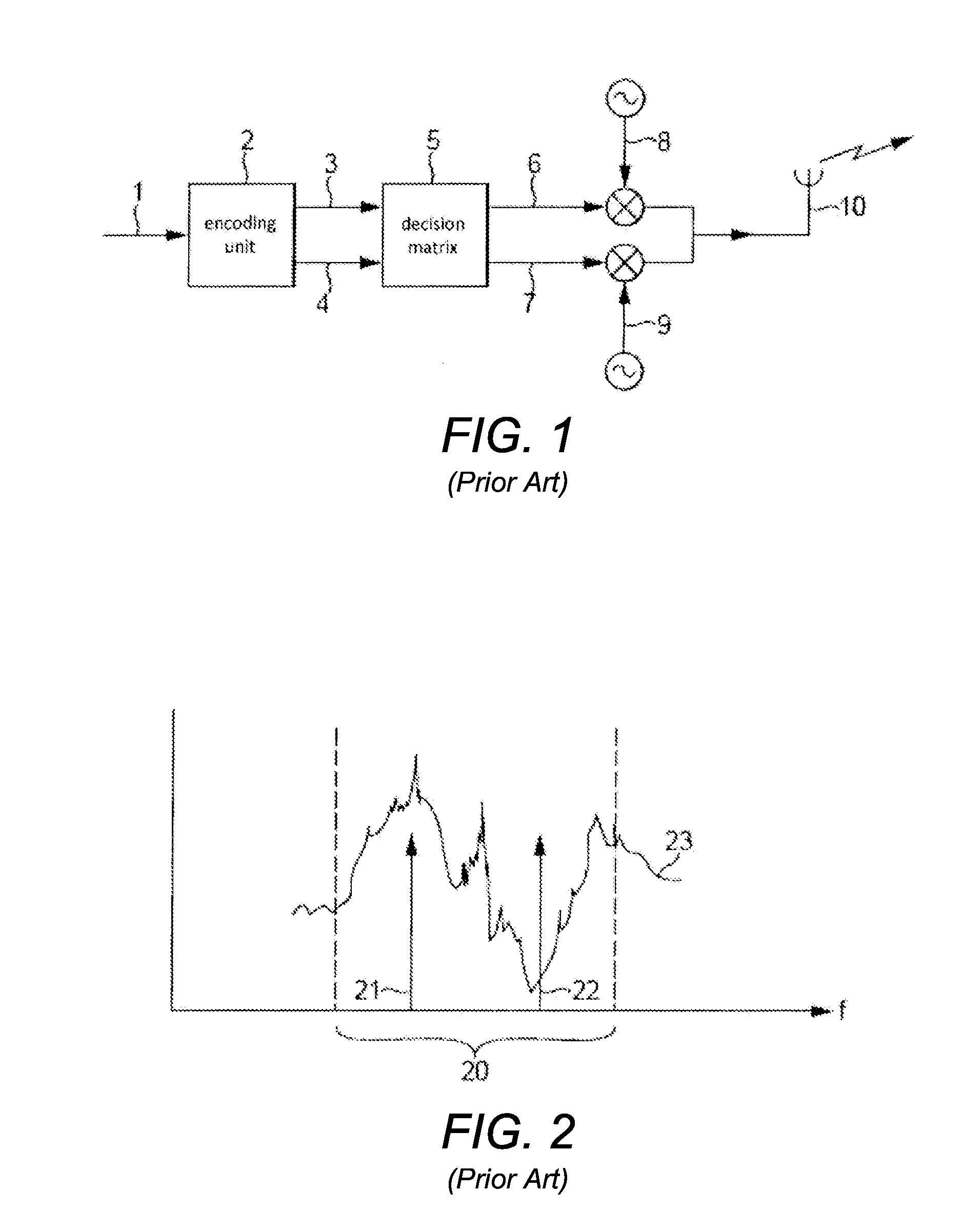
CROSS-REFERENCE TO RELATED APPLICATION[0001]This application is a continuation of application Ser. No. 12 / 397,483 filed Mar. 4, 2009 under 35 U.S.C. §120.BACKGROUND OF THE INVENTION[0002]The invention relates to a coding unit for determining how the amplitude and phase of two carrier signals should be modulated so as to transmit a data symbol by means of those carrier signals.[0003]FIG. 1 illustrates schematically the channel encoding system in one example of a dual carrier modulation (DCM) transmitter. A bit stream 1 for transmission is passed to an encoding unit 2 which generates two streams 3, 4 of QPSK (quaternary phase shift keyed) data. Those streams pass to a decision matrix 5 which generates two streams 6, 7 of 16 QAM (16 state quadrature amplitude modulation) data. The matrix 5 operates in such a way that both QAM streams are dependent on both QPSK streams, with the result that if either one of the QAM streams is received perfectly then a receiver can recover both QPSK stre...

Claims


Application Information

Patent Timeline
Patent Type & Authority Applications(United States)
IPC IPC(8): H04L27/00H04B7/02
CPCH04B7/02H04L1/0058H04L1/02H04L27/3405H04L27/2627H04L27/2649H04L1/08H04L27/26524
Inventor SELLER, OLIVIER BERNARD ANDRE
Owner CAMBRIDGE SILICON RADIO
Learn More