
Organic light emitting device and display unit including the same

a technology of light emitting devices and display units, applied in the direction of organic semiconductor devices, solid-state devices, semiconductor devices, etc., can solve the problems of major impact and disadvantage of lowering aperture ratio, and achieve the effect of improving aperture ratio and deteriorating device characteristics

Active Publication Date: 2012-10-04
SONY CORP
View PDF3 Cites 24 Cited by
  • Summary
  • Abstract
  • Description
  • Claims
  • Application Information

AI Technical Summary

Benefits of technology

[0005]It is desirable to provide an organic light emitting device capable of preventing disconnection of the organic layer and the second electrode and having a high aperture ratio and a display unit including the organic light emitting device.
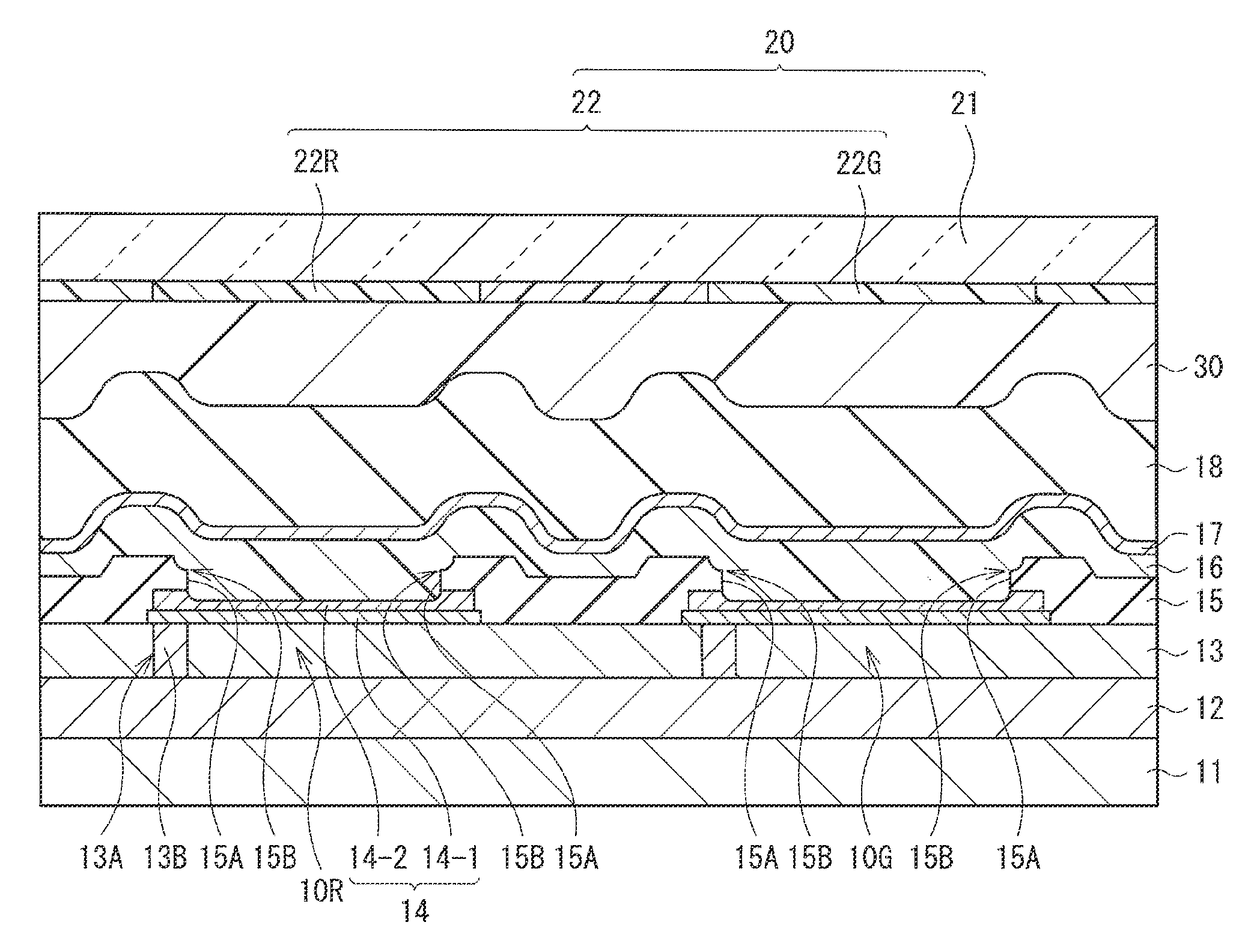
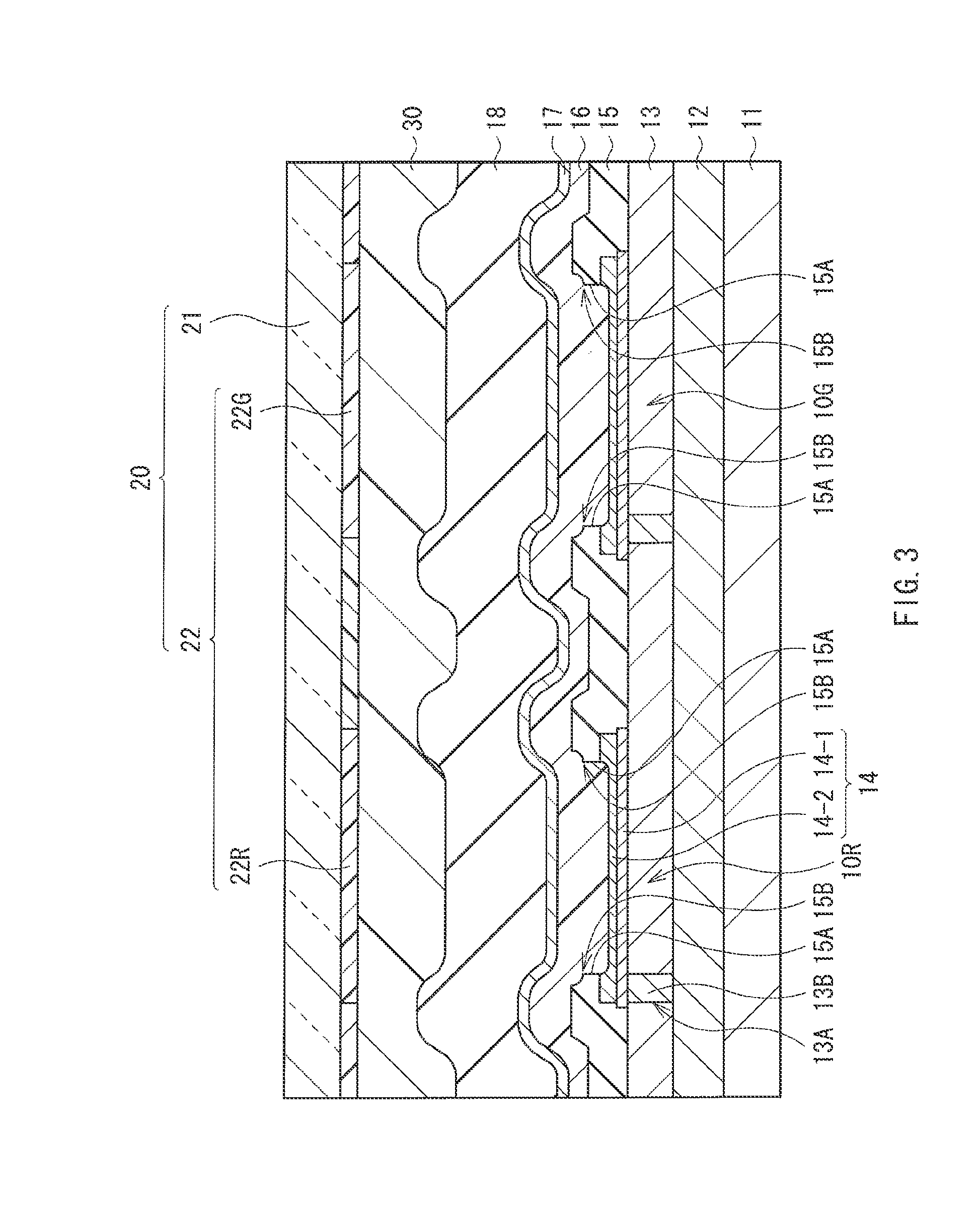
[0010]In the first organic light emitting device or the first display unit according to the embodiment of the technology, the internal wall surface of the insulating film (device separation film) being in contact with the organic layer has a plurality of faces each having different inclined angle with respect to the surface (horizontal surface) of the first electrode bounded by the corner section, that is, a relatively precipitous face on the first electrode side (first face) and one or more faces on the second electrode side with a relatively moderate inclined angle (second face). While the second face suppresses disconnection of the second electrode, the first face secures the aperture size.
[0012]In the first organic light emitting device and the first display unit according to the embodiment of the technology, one or more corner sections are provided in the internal wall surface of the insulating film as the device separation film. In the second organic light emitting device and the second display unit according to the embodiment of the technology, the inclined surface is provided in the insulating film as the device separation film. Therefore, deterioration of device characteristics due to disconnection of the organic layer and the second electrode is able to be prevented, and the aperture ratio is able to be improved.

Problems solved by technology

However, in the case where the foregoing moderately tapered-shaped insulating film is used, the first electrode is widely covered with the insulating film, leading to a disadvantage of a lowered aperture ratio.
In particular, in the case where such an insulating film is applied to a small and high-definition display unit, such a disadvantage has a major impact.

Method used


Image

  • Organic light emitting device and display unit including the same
  • Organic light emitting device and display unit including the same
  • Organic light emitting device and display unit including the same

Examples


first embodiment (

1. First embodiment (example that an insulating film has a corner section)

2. Modification (example that an insulating film has a plurality of corner sections)

second embodiment (

3. Second embodiment (example that an insulating film has an inclined surface)

application examples

4. Application examples

First Embodiment

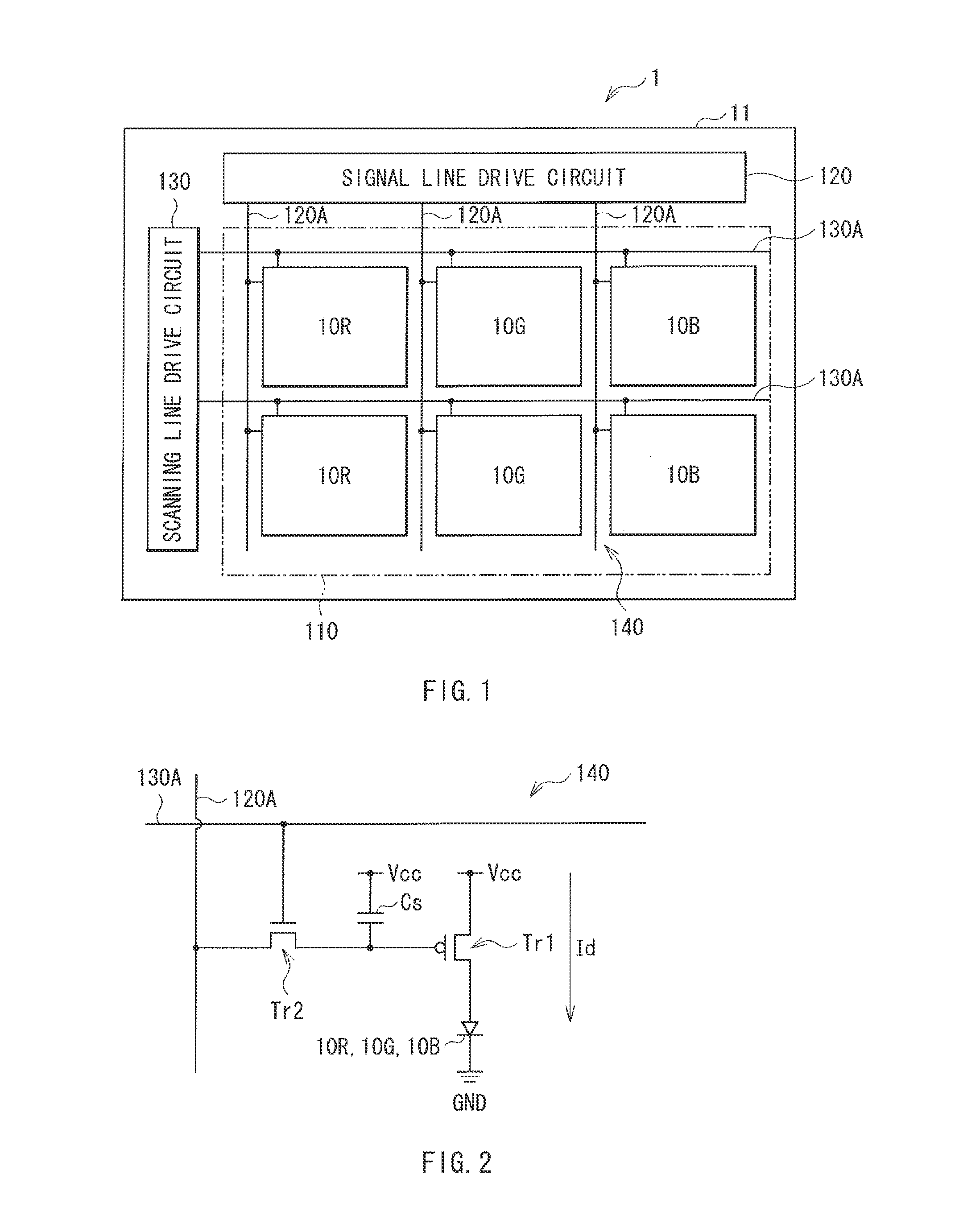
[0036]FIG. 1 illustrates a configuration of a display unit (display unit 1) according to an embodiment of the present disclosure. The display unit 1 is an organic EL (Electroluminescence) display unit. In the display unit 1, as a display region 110, a plurality of organic EL devices (organic light emitting devices) 10R, 10G and 10B are arranged in a matrix state over a substrate 11. The organic EL devices 10R, 10G, and 10B respectively generate red light (wavelength: from 620 nm to 750 nm both inclusive), green light (wavelength: from 495 nm to 570 nm both inclusive), and blue light (wavelength: from 450 nm to 495 nm both inclusive). A signal line drive circuit 120 and a scanning line drive circuit 130 to display an image are provided on the periphery of the display region 110.

[0037]In the display region 110, an active type drive circuit (pixel drive circuit 140) is provided. As illustrated in FIG. 2, the pixel drive circuit 140 has a drive tra...


PUM


Abstract

An organic light emitting device includes a first electrode and a second electrode, an organic layer including a light emitting layer between the first electrode and the second electrode, and an insulating film covering a rim of the first electrode from a surface thereof to a side surface thereof, and having an internal wall surface being in contact with the organic layer, and one or more corner sections in the internal wall surface with a ridge line thereof in parallel with the surface of the first electrode.

Description

BACKGROUND[0001]The present technology relates to an organic light emitting device having an insulating film as a device separation film under an organic layer and a display unit including the same.[0002]In recent years, as one of flat panel displays, an organic light emitting display using an organic light emitting device have attracted attentions. Since the organic light emitting display does not need a backlight, the thickness and the weight thereof are able to be decreased. Further, since the organic light emitting display is a self-luminous type display, the view angle is wide and the power consumption is low. Further, the organic light emitting display is regarded as a display having sufficient response to a high-definition and high-speed video signal. Therefore, development of the organic light emitting display has been advanced toward the practical use thereof.[0003]As a configuration of the organic light emitting device, for example, a configuration in which a first electro...

Claims


Application Information

Patent Timeline
IPC IPC(8): H01L51/50
CPCH01L27/3246H01L51/5218H01L51/5253H01L27/3248H01L27/3272H01L2251/5315H10K59/122H10K2102/3026H10K59/80518H10K59/873H10K59/876H10K59/30H10K59/123H10K59/126H10K50/818H10K50/844
Inventor YOKOYAMA, SEIICHIMAKITA, ATSUYAHASEGAWA, EIJIYAMADA, JIROSHIRAI, HIROHISAKOGA, YASUTAKAHIBARINO, SHINSUKE
Owner SONY CORP
Learn More