Device for power generation with large flow rate by small water-level difference

a technology of power generation and flow rate, applied in the direction of electric generator control, final product manufacture, machines/engines, etc., can solve the problem that the practical power plant cannot be made by efficiency and cos

Inactive Publication Date: 2012-10-04
IKEMURA MASAHIRO
View PDF5 Cites 22 Cited by
  • Summary
  • Abstract
  • Description
  • Claims
  • Application Information

AI Technical Summary

Benefits of technology

[0024]“Phase Difference Smooth Program” is the following, as for the 1st Tank to the 3rd Tank which are plural number, it is program which shifts cycle of feed-and-drain of each Tank, is made to open and close the Underwater Valve, and makes parallel operation, it is characterized by lessening instability of the amount of emergence of energy.
[0028]The Underwater Valves of the 1st Tank-the 3rd Tank equips the Specific-gravity Valve, as for the 1st Specific-gravity Valve, that Underwater Valve is driven from upside water, that movable Structure is equipped with the weight of balance structure of a pulley or seesaw, the underwater weight of that Underwater Valve and that upside water weight are balanced nearly, hence, the underwater Specific-gravity of the Underwater Valve resembles the Specific-gravity of water, as for the 2nd Specific-gravity valve, this Underwater Valve equips emptiness structure made to resemble to the Specific-gravity of water, as for the structure of the aforesaid 1st Specific-gravity Valve and the aforesaid 2nd Specific-gravity Valve, this reduces the drive bottleneck of opening and closing by own weight, and it is movable with few streams, above is the Specific-gravity Valve Mechanism.

Problems solved by technology

As for the conventional low water level difference, the water-wheel cannot handle the large flow because the fluid friction is large, a practical power plant was not able to be made by efficiency and cost.

Method used


Image

  • Device for power generation with large flow rate by small water-level difference
  • Device for power generation with large flow rate by small water-level difference
  • Device for power generation with large flow rate by small water-level difference

Examples


Embodiment Construction

[0130]This invention is the mechanism of a supplement of “Japanese Patent Application No.2005-154588”.

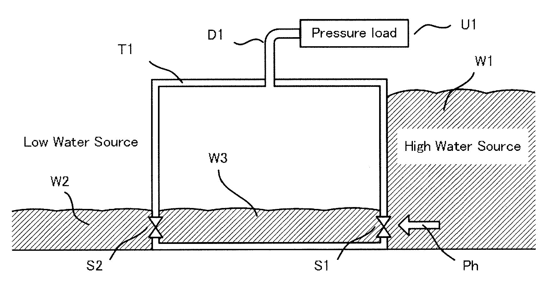
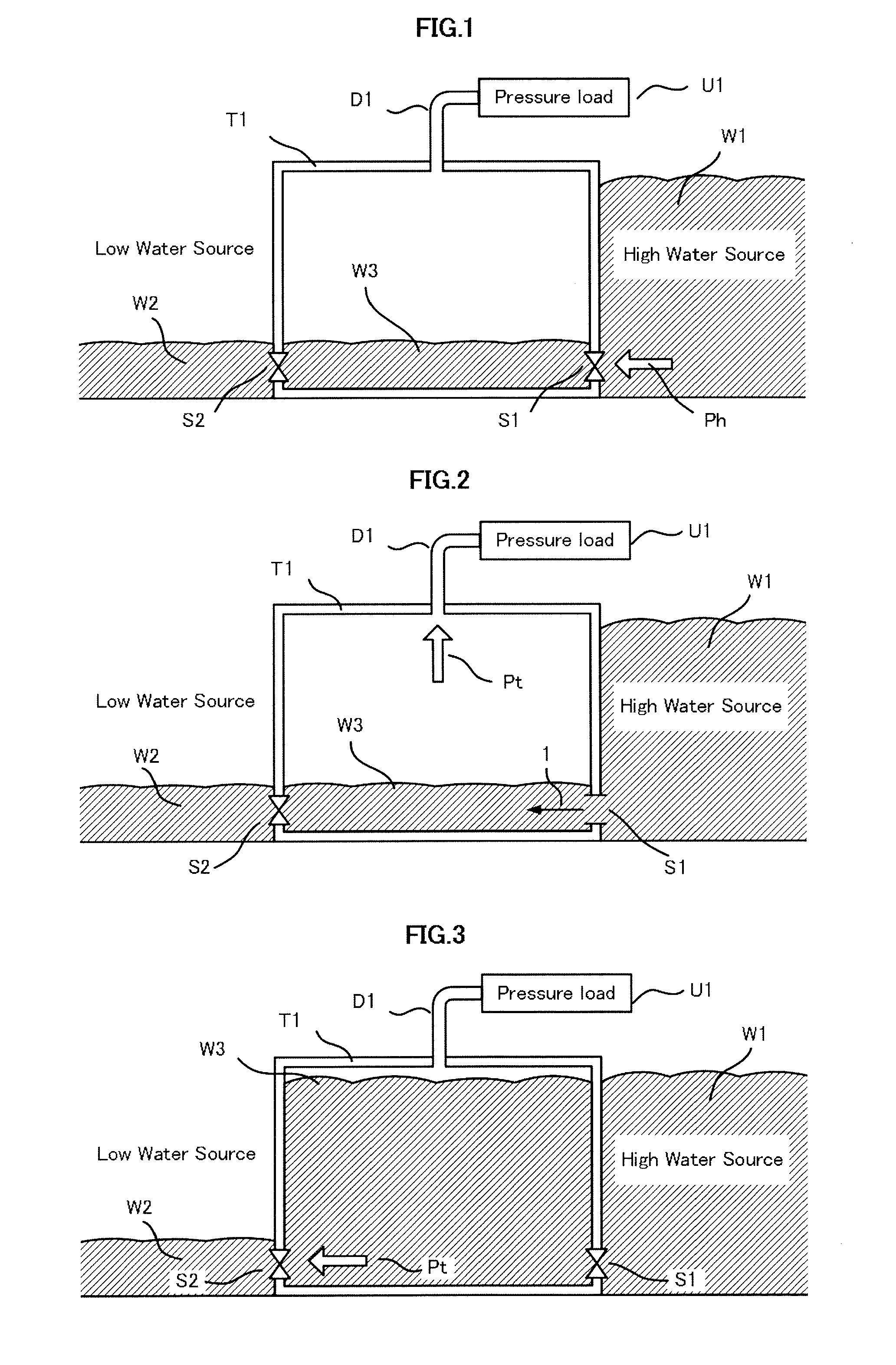
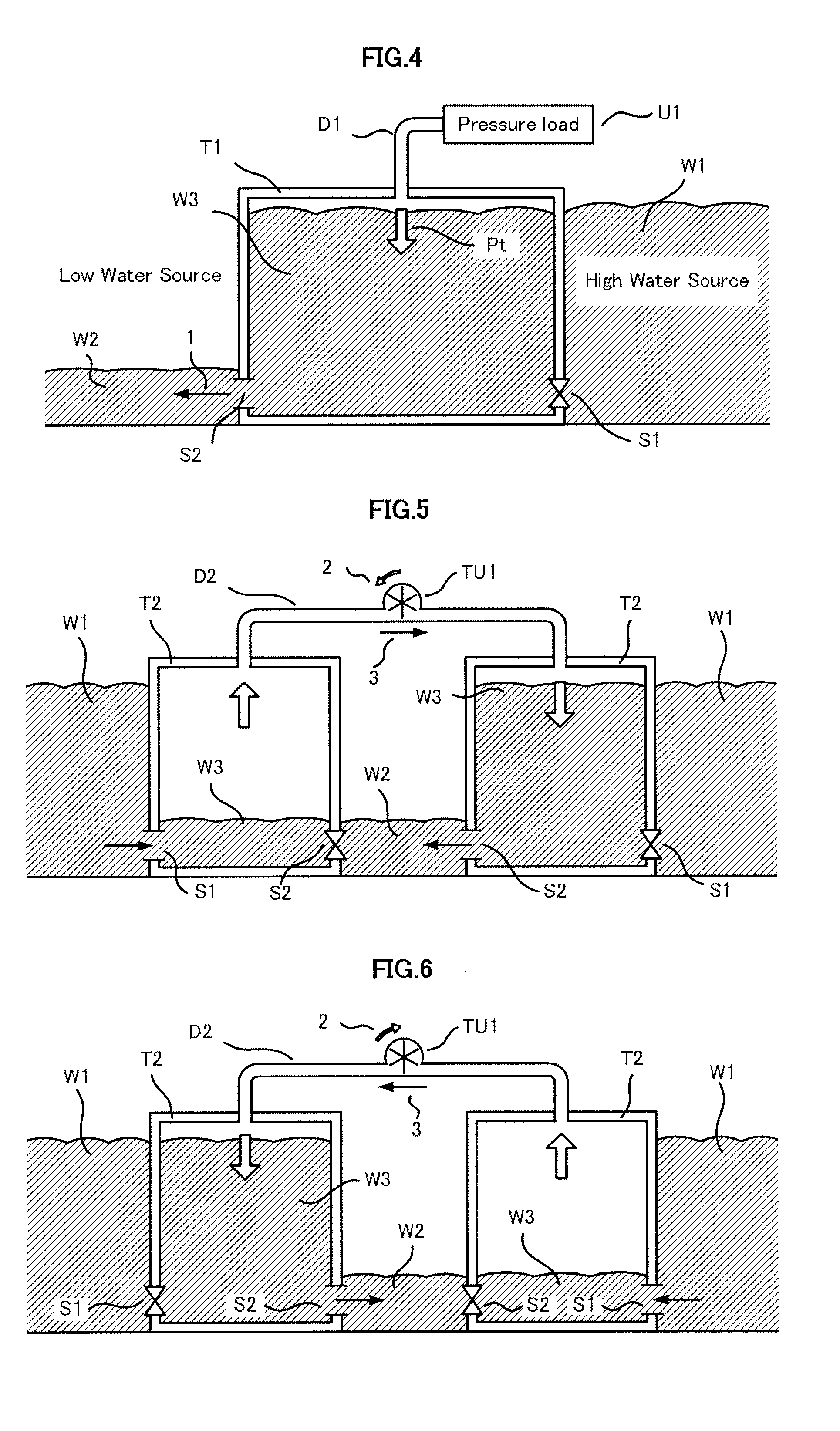
[0131]As for the Tank of FIGS. 1-4, 7-9, the external Pressure Load of the Pressure Occurrence Mechanism (U1) can be utilized for the power of the drive by the occurrence pressure of the Open Air Duct (D1). As for the Tank of FIGS. 1-9, the torque can be intermittently obtained by repetition of feed water and drain if the bidirectional movable turbine is used for the Passage Duct, the 1st Tanks (T1) of FIGS. 1-4 are a basic form of the principle of this invention. The Water Sources in figures are very large compared with the Tanks if actual, the delineation which valve in the figures cannot be seen by the Flow Path shows the open condition of the valves. The same Water Source of the drawing separated all over the figure is connected.

[0132]As for FIGS. 1-4, the 1st Tank (T1) is located between the High Water Source (W1) and the Low Water Source (W2). As for FIG. 2, it becomes supplyi...


PUM


Abstract

As for the floodgate which it flows into one-way from a tide level, the High Water Source flowing in is made, and the Low Water Source flowing out is made. A tank is located between these Water Sources, repetition of the feed water from a high-water level, and the drain to a low-water level, it generates electricity by rotating a air turbine by the pressure in a Tank. As for the method of the improvement in efficiency, a turbine is set to Air Duct between two sets of tanks, the double electric power is obtained by interlocking with opposite feed water and drain. Moreover, the variation of electric power is improved by shifting the cycle of the tank of parallel movement. And it responds to water level in a tank, the stable production of electricity is obtained by the drive of selection of the turbine of the capacity difference of a parallel drive. If this mechanism is opened and closed with the underwater valve of a big flow, it becomes possible to obtain the big electric power. The underwater valve of the Specific-gravity near water is made into locking mechanism, locking is canceled at the case of opening, the valve closed by own weight when a stream stops, thereby, a big flow is made to control with energy conservation. Moreover, there is attachment of efficiency improvement mechanism and the increase difference mechanism of Water Sources in this invention.

Description

BACKGROUND OF THE INVENTION[0001]1. Field of the Invention[0002]This invention is an example of evolution of the Japanese patent 2005-154588, the High Water Source is made from the high tide inflow, the Low Water Source is made from the outflow to ebb tide, this is the hydroelectric power generation using that water level difference, moreover, hydroelectric power generation can be performed also in the river which can be made the water source with the water level difference.[0003]2. Description of Related Art[0004]As for the conventional low water level difference, the water-wheel cannot handle the large flow because the fluid friction is large, a practical power plant was not able to be made by efficiency and cost. As for the power generation by the air-turbine attached to the Tank, the power plant of big electric power becomes possible by the Big Flow Underwater Valve driven with little energy.[0005]Patent Document 1: Japanese Patent Application No.H08-227317[0006]Patent Document ...

Claims


Application Information

Patent Timeline
Patent Type & Authority Applications(United States)
IPC IPC(8): F03B13/08
CPCF03B13/26Y02E10/38Y02E10/28F03B13/268Y02E10/30Y02P70/50Y02E10/20
Inventor IKEMURA, MASAHIRO
Owner IKEMURA MASAHIRO
Why Eureka
Try Eureka