Driver device, print head, and image formation apparatus

Inactive Publication Date: 2012-10-04
OKI DATA CORP
View PDF3 Cites 2 Cited by
  • Summary
  • Abstract
  • Description
  • Claims
  • Application Information

AI Technical Summary

Benefits of technology

[0009]To achieve faster operations, the print head is provided with multiple self-scan type thyristor-array chips, which are designed to operate simultaneously in parallel. Two clocks are used as the data-transfer clocks to the thyristor-array chips, and two clocks are inputted for each thyristor-array chip. Hence, the clock-driver circuit of each self-scan type print head needs four output terminals for driving each thyristor-array chip.
[0011]There has been a demand for a circuit configuration capable of generating clocks for the self-scan type light emission-element array chips without increasing the number of terminals which can be accommodated in an LSI package to drive the print head.
[0018]According to the first to the fourth aspects, the first, second and third clock pulses outputted from the clock-driver circuit are subjected to waveform shaping performed by the waveform-shaper circuit to generate the first and second clocks, and the first and second clocks are used to drive the scan-circuit portion. Hence, the number of output terminals in the clock-driver circuit can be reduced from what the conventional technique needs to have. Accordingly, not only can an improvement in the data-transfer speed of the print head be achieved, but also the reduced number of output terminals of the clock-driver circuit can contribute to the scaling-down of the circuit and to a cost reduction as a result of the scaling down.
[0019]According to the fifth and sixth aspects, the use of the print head of the second and fourth aspects helps provide a high-quality image formation apparatus that has both an excellent space efficiency and an excellent light-extraction efficiency.

Problems solved by technology

The conventional self-scan type print head needs two output terminals for each transfer clock in the clock-driver circuit, and, as a result, has the following problems.
This causes a problem of the incapability of speeding-up the operations of the print head.

Method used


Image

  • Driver device, print head, and image formation apparatus
  • Driver device, print head, and image formation apparatus
  • Driver device, print head, and image formation apparatus

Examples


first embodiment

(Printer-Controller Circuit of First Embodiment)

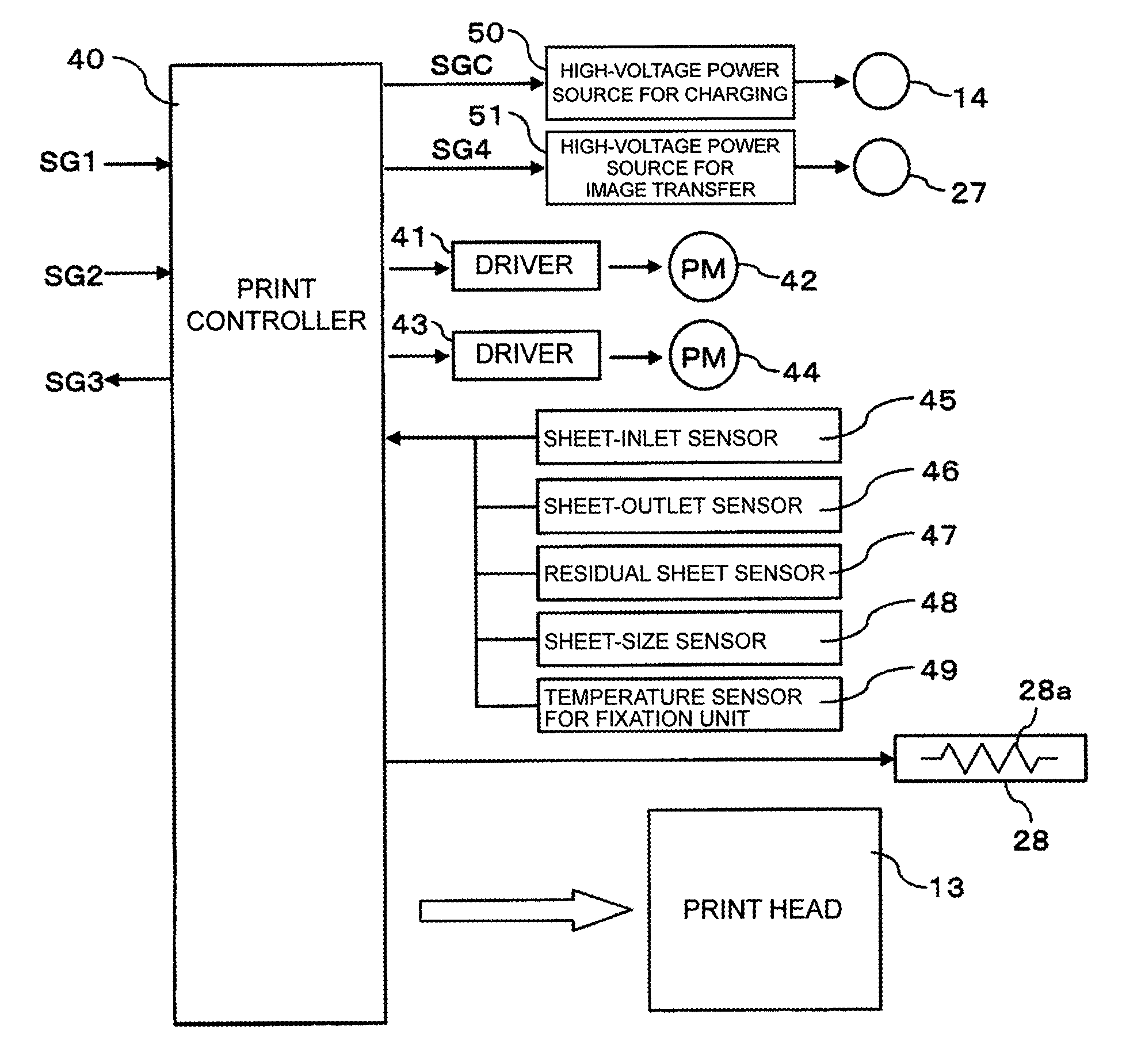
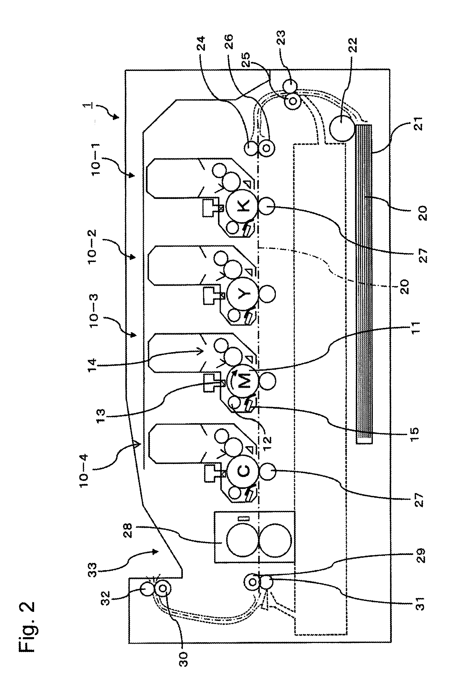
[0042]FIG. 5 is a block diagram schematically illustrating the configuration of the printer-controller circuit in image formation apparatus 1 shown in FIG. 2. For the sake of a simpler explanation, FIG. 5 illustrates a configuration to control one of the four process units (e.g., process unit 10-3 of magenta color).

[0043]The printer-controller circuit shown in FIG. 5 includes print controller 40 placed inside of the print portion of image formation apparatus 1. Print controller 40 includes, among other things, a microprocessor, a read-only memory (ROM), a random access memory (RAM), a timer, and an input / output port through which signals are received and outputted. The printer-controller circuit has a function of making image formation apparatus 1 perform print operations by executing sequence control of the entire printer with control signals SG1, video signals (i.e., one-dimensionally-arranged dot-map data) SG2 and the like coming fr...

second embodiment

[0132]The circuit configurations of the print head and print controller of image formation apparatus 1 according to a second embodiment of the invention are different from the circuit configurations of print head 13 and print controller 40 of the first embodiment. Descriptions are given of what makes the second embodiment different from the first embodiment.

(Print Controller and Print Head of Second Embodiment)

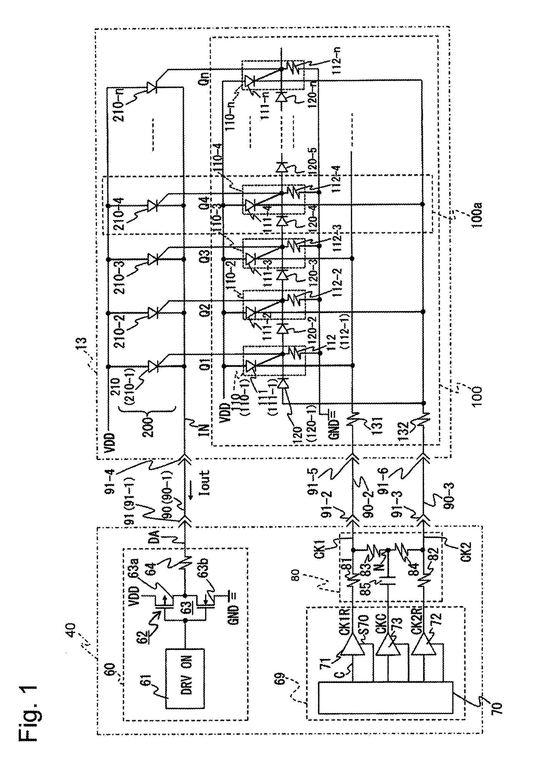
[0133]FIG. 9 is a block diagram schematically illustrating the circuit configurations of the print controller and the print head according to the second embodiment of the invention. Elements that are the same as those in FIG. 1 showing the circuit configurations of the first embodiment are denoted by the same reference numerals as are used in FIG. 1.

[0134]Image formation apparatus 1 of the second embodiment includes, among other things, multiple print heads 13 (i.e., 13-1 to 13-n; e.g., n=13-1, 13-2, . . . , 13-6, . . . ), and print controller 40A configured to control print h...

second embodiments

Modifications of First and Second Embodiments

[0172]The invention is not limited to the first and second embodiments, and can be carried out in other use modes and modifications. The following cases (I) and (II) are examples of such use modes and modifications.

[0173](I) The cases where the invention is applied to light emission thyristors 210 used as light sources are described for the first and second embodiments. The invention is also applicable to cases where thyristors are used as switching elements and a voltage-application control is performed to apply voltage to other elements—e.g., organic electroluminescence elements (hereinafter simply referred to as “organic EL elements”), display elements, or the like)—connected, for example in series, as the switching elements. For example, the invention can be used, among other things, in a printer equipped with an organic EL print head including an array of organic EL elements, and in a display apparatus including rows of display eleme...


PUM


Abstract

A driver device scans and drives light emission elements arranged in a branch connection to a common terminal using scan-circuit and data drive portions and clock driver and waveform shaper circuits. The scan circuit portion has scan circuits connected cascadely to one another with output terminals connected to the light emission elements. The driver device outputs first and second clock signals to odd- and even-numbered scan circuits respectively. The light emission elements are sequentially driven from a first to a last scan circuit when the second-clock signal is applied to the first scan circuit. The data-drive portion drives the common terminal. The clock-driver circuit outputs first and second clock pulses with different phases, and a third-clock pulse synchronized with the first and second clock pulses. The waveform-shaper circuit re-shapes the waveforms of the clock signals.

Description

CROSS REFERENCE TO RELATED APPLICATIONS[0001]This application claims priority based on 35 USC 119 from prior Japanese Patent Application No. 2011-075914 filed on Mar. 30, 2011, entitled “DRIVER DEVICE, PRINT HEAD, AND IMAGE FORMATION APPARATUS”, the entire contents of which are incorporated herein by reference.BACKGROUND OF THE INVENTION[0002]1. Field of the Invention[0003]The present disclosure relates to a driver device to drive multiple light emission elements, a print head including the driver device, and an image formation apparatus.[0004]2. Description of Related Art[0005]Some conventional image formation apparatuses using electrophotography include an exposure portion formed by arranging multiple light emission thyristors as light emission elements. In such conventional image formation apparatuses that employ light emission thyristors, (of a number N where N>1), the light emission thyristors are provided per driver circuit. In addition, the position of a light emission thy...

Claims


Application Information

Patent Timeline
IPC IPC(8): B41J2/435H05B37/02
CPCG03G15/043H04N1/1938G06K15/1894G06K15/1247H04N2201/0082
Inventor NAGUMO, AKIRA
Owner OKI DATA CORP
Why Eureka
Try Eureka