Internal combustion engine use ignition device

Active Publication Date: 2021-12-09
MITSUBISHI ELECTRIC CORP
View PDF0 Cites 0 Cited by
  • Summary
  • Abstract
  • Description
  • Claims
  • Application Information

AI Technical Summary

Benefits of technology

The present application relates to an ignition device for internal combustion engines that provides a common input terminal for two driving signals. This reduces the number of signal lines and allows for a smaller and less expensive ignition device. Additionally, the number of output terminals from the electronic control unit (ECU) is reduced by the number of cylinders, further reducing size and cost. The patent includes circuit diagrams and operational waveforms for the different embodiments of the ignition device. These effects make the device more efficient and cost-effective for use in internal combustion engines.

Problems solved by technology

However, because the air-fuel mixture of the internal combustion engine which is made to operate in the lean state or in the high EGR state does not present a good ignitability, a higher energy state, especially a higher electric current state, is required in the ignition device.

Method used


Image

  • Internal combustion engine use ignition device
  • Internal combustion engine use ignition device
  • Internal combustion engine use ignition device

Examples


embodiment 1

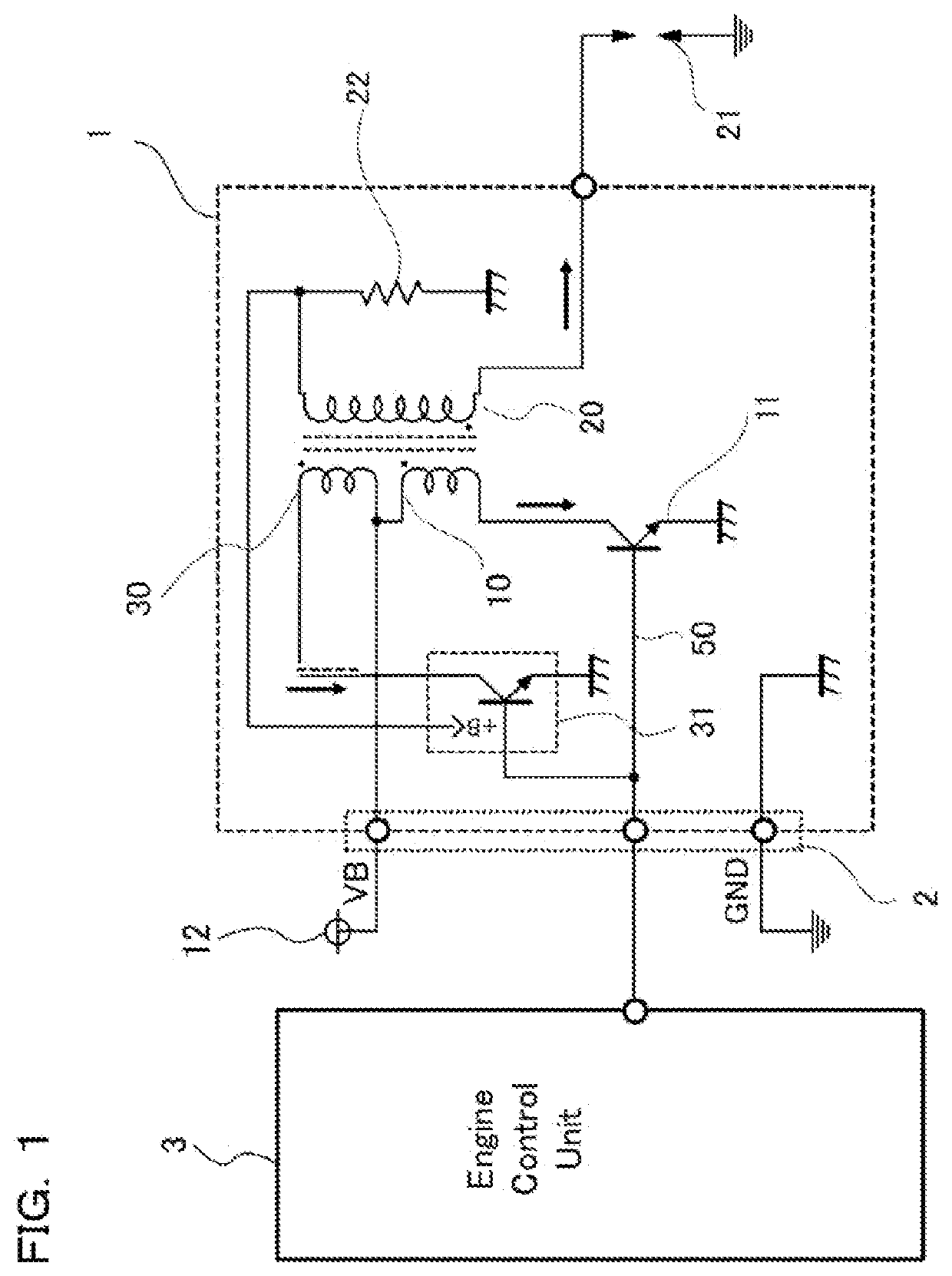
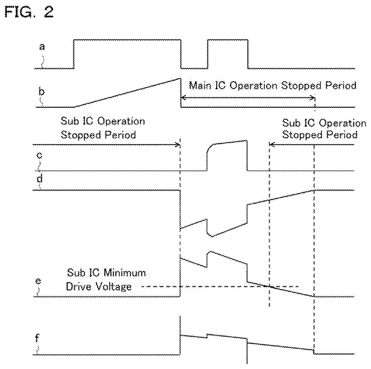
[0032]FIG. 1 is a circuit diagram which shows an internal combustion engine use ignition device, in accordance with Embodiment 1 of the present application. Further, FIG. 2 is a drawing for showing operational waveforms in the circuit diagram of FIG. 1, where the circuit is under basic conditions.

[0033]In the internal combustion engine use ignition device in accordance with Embodiment 1, as is shown in FIG. 1, the primary coil of an ignition coil is divided, in the middle point, into a main primary coil 10 and a sub primary coil 30, and a current from a power source 12 is supplied to the middle point through an ignition device input connector 2. Further, the switching between on and off for the electrical connection of the main primary coil 10 is performed with a main IC 11 (switch element) which is connected to the main primary coil 10.

[0034]When the main IC 11 is turned on, a current will flow into the main primary coil 10, and a magnetic flux by applied electric current is produc...

embodiment 2

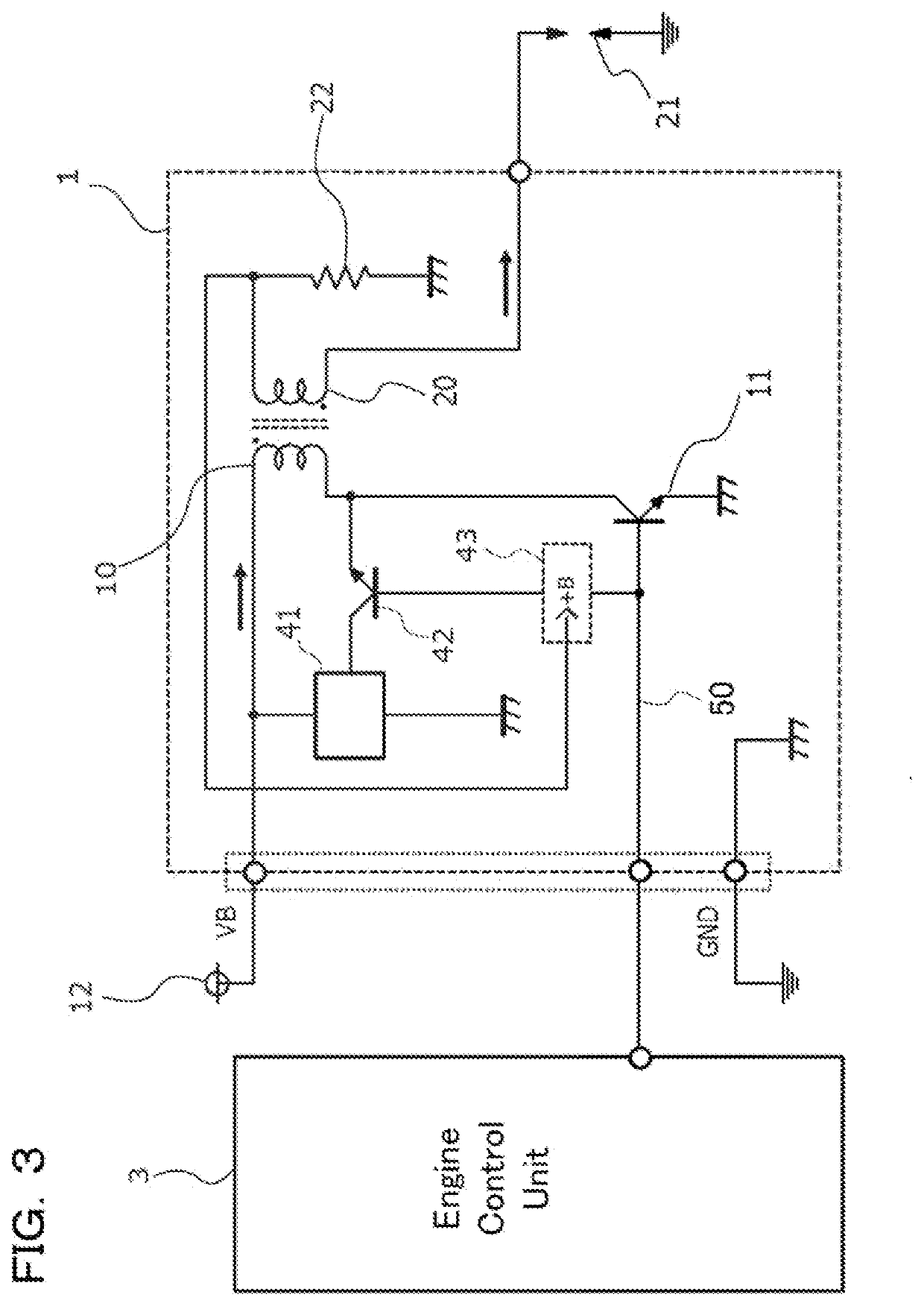
[0047]FIG. 3 is a circuit diagram which shows an internal combustion engine use ignition device, in accordance with Embodiment 2 of the present application. Further, FIG. 4 is a drawing for showing operational waveforms in the circuit diagram of FIG. 3, where the circuit is under basic conditions.

[0048]As shown in FIG. 3, the internal combustion engine use ignition device in accordance with Embodiment 2 includes a main primary coil 10; a main IC 11 which is connected to the main primary coil 10, and has functions to switch between the power feeding to the main primary coil 10 and its shut off, and to detect between its own c and e terminals (the collector and the emitter), and to stop its own operation at the time when a voltage is generated between the c and e terminals; a primary side step up power source 41 which performs a step up operation using a VB voltage (reference voltage); a primary side switch element 42 which is disposed at the collector terminal of the main IC 11, in p...

embodiment 3

[0056]FIG. 5 is a circuit diagram showing the internal combustion engine use ignition device in accordance with Embodiment 3 of the present application. Further, FIG. 6 is a drawing for showing operational waveforms in the circuit diagram of FIG. 5, where the circuit is under basic conditions.

[0057]As shown in FIG. 5, the internal combustion engine use ignition device in accordance with Embodiment 3 is provided with a main primary coil 10; a main IC 11 which is connected to the main primary coil 10, and has functions to switch between the power feeding to the main primary coil 10 and its shut off, and to detect between its own c and e terminals (the collector and the emitter), and to stop its own operation at the time when a voltage is generated between the c and e terminals; a secondary side step up power source 51 which performs a step up operation using a VB voltage; a secondary coil 20 which is connected to the ignition plug 21 at one end, and is connected to the secondary curre...


PUM


Abstract

In an internal combustion engine use ignition device includes an ignition coil which has a primary coil and a secondary coil, that are wound around a core, a superimpose circuit which generates an output energy, that is to be superimposed with respect to a secondary current, produced in the secondary coil by the primary coil, a first switch element which is connected to the primary coil and turns on or off of a current to the primary coil, a second switch element which is connected to the superimpose circuit, and stops an operation in a case where the first switch element is turned on, and performs an operation in a case where the first switch element is turned off, and a common input terminal which receives a first driving signal for driving the first switch element and a second driving signal for driving the second switch element.

Description

FIELD OF THE INVENTION[0001]The present application relates to an internal combustion engine use ignition device.BACKGROUND OF THE INVENTION[0002]Internal combustion engine use ignition devices are provided with a primary coil whose high voltage side terminal of one end is connected to a direct current power source, and a secondary coil which is wound around by secondary winding turns, the number of which is in a predetermined winding turns ratio, with respect to the primary coil; and are the ones in which a high secondary voltage is generated in the secondary coil by the increase and decrease of a primary current which flows into the primary coil, and energy is supplied to an ignition plug that is attached to one end of this secondary coil, and a spark discharge is generated.[0003]An existing internal combustion engine use ignition device (hereinafter, referred to as an ignition device, for short) plays a role to convert a low voltage of a direct current power source into a high vo...

Claims


Application Information

Patent Timeline
IPC IPC(8): H01F38/12F02P3/04
CPCH01F38/12F02P3/04F02P3/053F02P15/12
Inventor MURAMOTO, YUICHIKATAOKA, NAOKI
Owner MITSUBISHI ELECTRIC CORP
Why Eureka
Try Eureka