Monolithic ceramic electronic component

a technology of monolithic ceramic and electronic components, applied in the direction of fixed capacitor details, stacked capacitors, fixed capacitors, etc., can solve the problems of large amount of time and effort required to develop ceramic materials having higher performance, inability to obtain and difficulty in achieving high performance and high humidity resistance. , to achieve the effect of increasing the humidity resistance of monolithic ceramic electronic components and increasing the heterogeneous region in the third direction

Active Publication Date: 2012-10-04
MURATA MFG CO LTD
View PDF7 Cites 35 Cited by
  • Summary
  • Abstract
  • Description
  • Claims
  • Application Information

AI Technical Summary

Benefits of technology

[0010]To overcome the problems described above, preferred embodiments of the present invention provide a monolithic ceramic capacitor having a small size, high performance, and high humidity resistance.

Problems solved by technology

However, a large amount of time and efforts are required to develop the ceramic material having higher performance.
When attempting to reduce a gap portion in which the inner electrodes are not disposed, so as to increase the area in which inner electrodes are opposed to each other, humidity resistance cannot be obtained at a sufficiently high level in some cases.
In other words, there has been a problem in that it is difficult to obtain high performance and high humidity resistance.

Method used


Image

  • Monolithic ceramic electronic component
  • Monolithic ceramic electronic component
  • Monolithic ceramic electronic component

Examples


first preferred embodiment

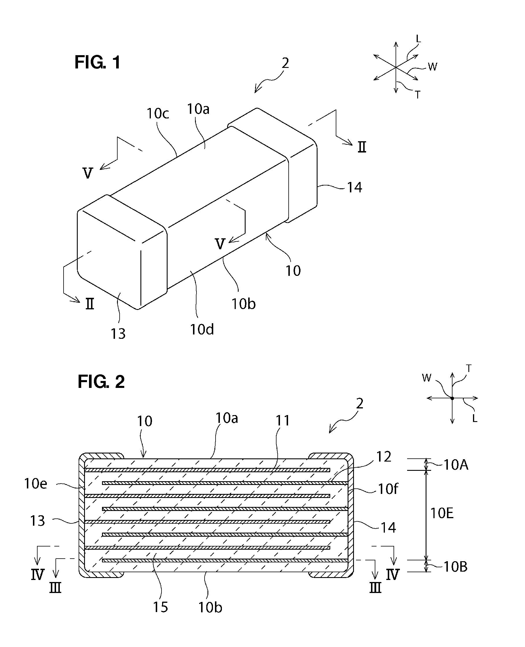
[0045]A ceramic electronic component 2, illustrated in FIG. 1, will be described below as one of the preferred embodiments of the present invention. However, it is to be noted that the ceramic electronic component of the present invention is not limited to the ceramic electronic component 2.

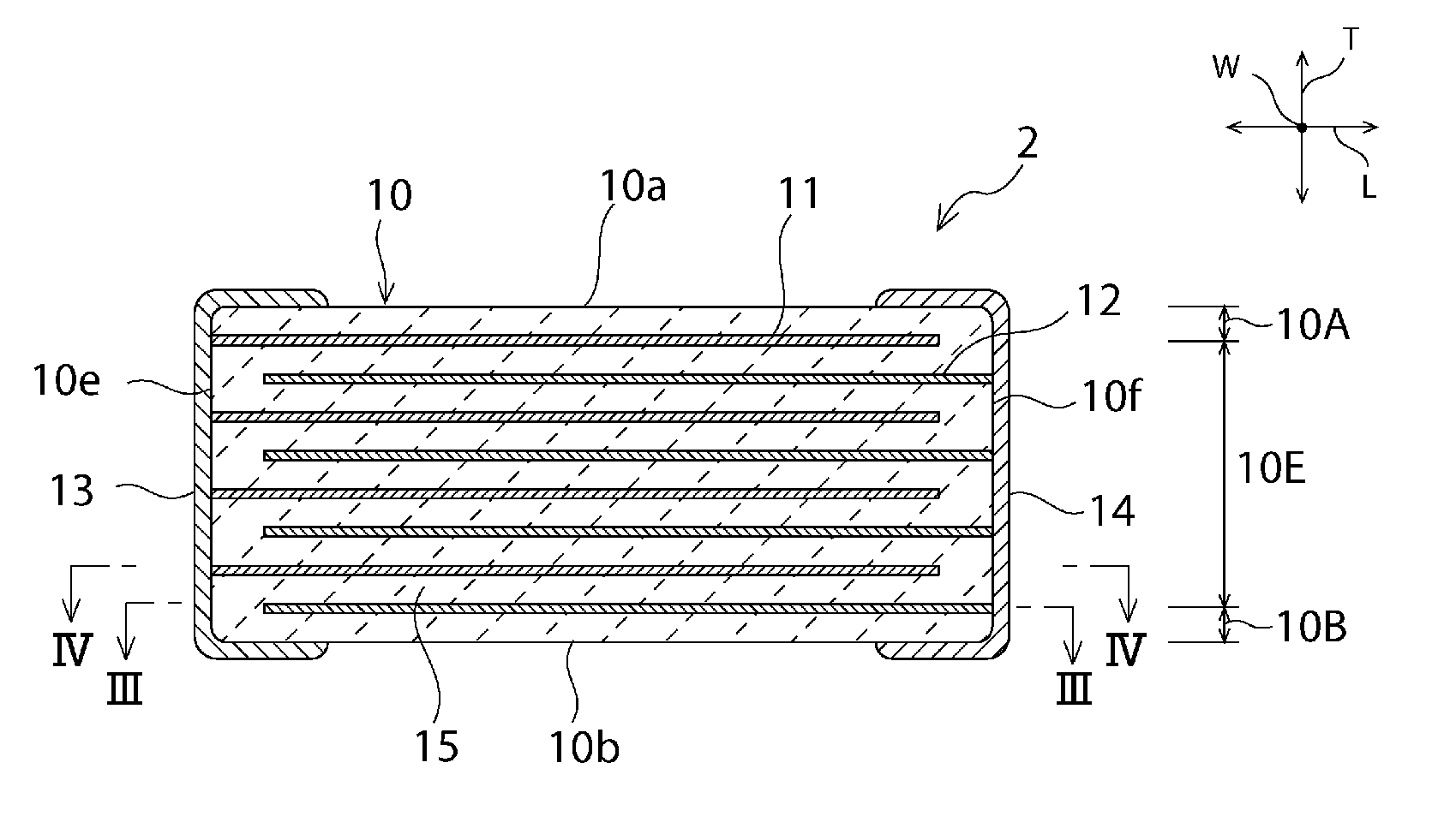
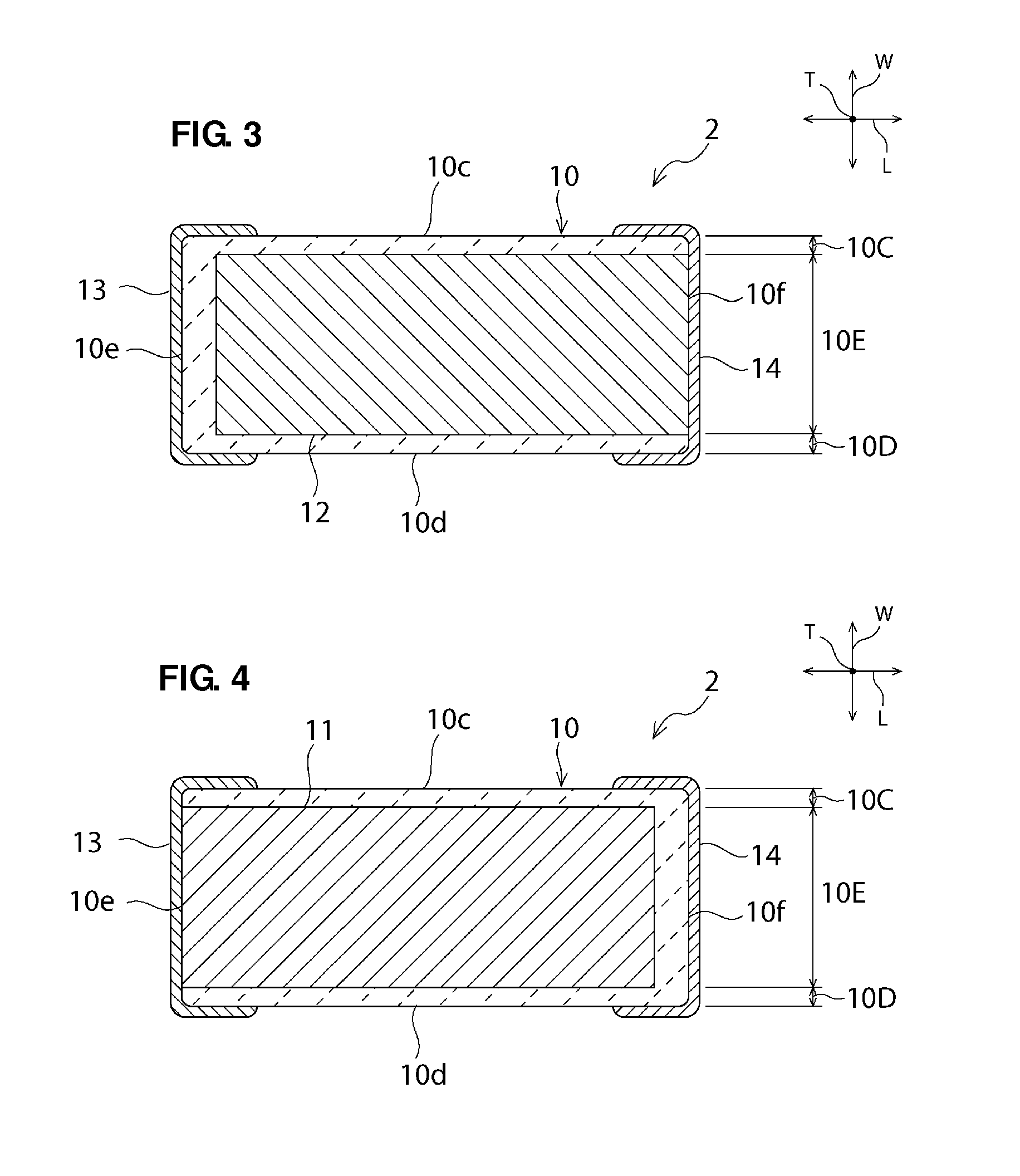
[0046]FIG. 1 is a schematic perspective view of a ceramic electronic component according to a first preferred embodiment of the present invention. FIG. 2 is a schematic sectional view taken along a line II-II in FIG. 1. FIG. 3 is a schematic sectional view taken along a line III-III in FIG. 2. FIG. 4 is a schematic sectional view taken along a line IV-IV in FIG. 2. FIG. 5 is a schematic sectional view taken along a line V-V in FIG. 1. FIG. 6 is an enlarged schematic sectional view of a portion VI in FIG. 5. FIG. 7 is an enlarged schematic sectional view of a portion VII in FIG. 5.

[0047]As illustrated in FIG. 1, the ceramic electronic component 2 according to the present preferred embodiment prefe...

second preferred embodiment

[0099]A ceramic electronic component 1, illustrated in FIG. 13, will be described below as another one of preferred embodiments of the present invention. However, it is to be noted that the ceramic electronic component of the present invention is not limited to the ceramic electronic component 1. In the following description of a second preferred embodiment of the present invention, members having functions substantially in common to those in the first preferred embodiment are denoted by common symbols.

[0100]FIG. 13 is a schematic perspective view of the ceramic electronic component according to the present preferred embodiment. FIG. 14 is a schematic sectional view taken along a line II-II in FIG. 13. FIG. 15 is a schematic sectional view taken along a line III-III in FIG. 13. FIG. 16 is a schematic sectional view taken along a line IV-IV in FIG. 13.

[0101]As illustrated in FIG. 13, the ceramic electronic component 1 according to the present preferred embodiment preferably includes ...


PUM

PropertyMeasurementUnit
thicknessaaaaaaaaaa
lengthaaaaaaaaaa
grain sizeaaaaaaaaaa

Abstract

An electronic component includes a ceramic sintered body, and a plurality of first and second inner electrodes alternately arranged inside the ceramic sintered body to be opposed to each other in a third direction with a ceramic layer interposed between the adjacent first and second inner electrodes. The first and second inner electrodes are each arranged to be exposed to a third or fourth surface without being exposed to fifth and sixth surfaces. Heterogeneous regions, which include solid solutions of metals included in the first and second inner electrodes and the ceramic sintered body, are arranged continuously in opposite end portions of the ceramic sintered body in a first direction to extend from one side end to an opposite side end of a region where the first and second inner electrodes are disposed in a third direction.

Description

BACKGROUND OF THE INVENTION[0001]1. Field of the Invention[0002]The present invention relates to a monolithic ceramic electronic component. In particular, the present invention relates to a monolithic ceramic electronic component including a ceramic sintered body including a plurality of first and second inner electrodes that are alternately disposed inside the ceramic sintered body to be opposed to each other with a ceramic layer interposed between the adjacent first and second inner electrodes.[0003]2. Description of the Related Art[0004]Monolithic ceramic electronic components, e.g., monolithic ceramic capacitors, have been used in many electronic devices, such as cellular phones and notebook personal computers.[0005]A trend toward smaller sizes and larger capacities of monolithic ceramic capacitors has recently increased. Even in power supply circuits, for example, in which aluminum electrolytic capacitors and tantalum capacitors have been primarily used to date, monolithic cera...

Claims


Application Information

Patent Timeline
Patent Type & Authority Applications(United States)
IPC IPC(8): H01G4/12
CPCH01G4/12H01G4/30H01G4/232H01G4/005H01G4/228H01L41/083H10N30/50
Inventor YAMASHITA, YASUHARU
Owner MURATA MFG CO LTD
Why Eureka
Try Eureka