Transmission controlling method, sender apparatus and receiver apparatus for wireless communication system

a wireless communication system and transmitter technology, applied in the direction of multi-channel communication, wireless communication, digital transmission, etc., can solve the problems of b>200/b>, the separation and synthesis of signals by the receiver apparatus may be difficult, and the inability to achieve high throughpu

Active Publication Date: 2012-10-04
FUJITSU LTD
View PDF6 Cites 11 Cited by
  • Summary
  • Abstract
  • Description
  • Claims
  • Application Information

AI Technical Summary

Benefits of technology

[0067]With the present invention, at least such an effect and an advantage as described just below are obtained.
[0068]In particular, also in a case wherein the number of transmission streams between the sender apparatus and the receiver apparatus varies (decreases) as in a case wherein the transmission mode is changed over from the MIMO multiplex transmission to non-MIMO multiplex transmission (MIMO diversity transmission or the like), since competition of data block identification does not occur between the transmission streams, re-sending in error of a data block from the sender apparatus and synthesis in error of the data block in the receiver apparatus can be avoided. Accordingly, normal communication (stream transmission) can be continued between the sender apparatus and the receiver apparatus.

Problems solved by technology

This is because, in the case of the line-of-sight communication, since an inter-antenna correlation occurs, there is the possibility that separation and synthesis of signals by the receiver apparatus 200 may be difficult and a high throughput cannot be obtained.

Method used


Image

  • Transmission controlling method, sender apparatus and receiver apparatus for wireless communication system
  • Transmission controlling method, sender apparatus and receiver apparatus for wireless communication system
  • Transmission controlling method, sender apparatus and receiver apparatus for wireless communication system

Examples


first embodiment

[A] Description of the First Embodiment

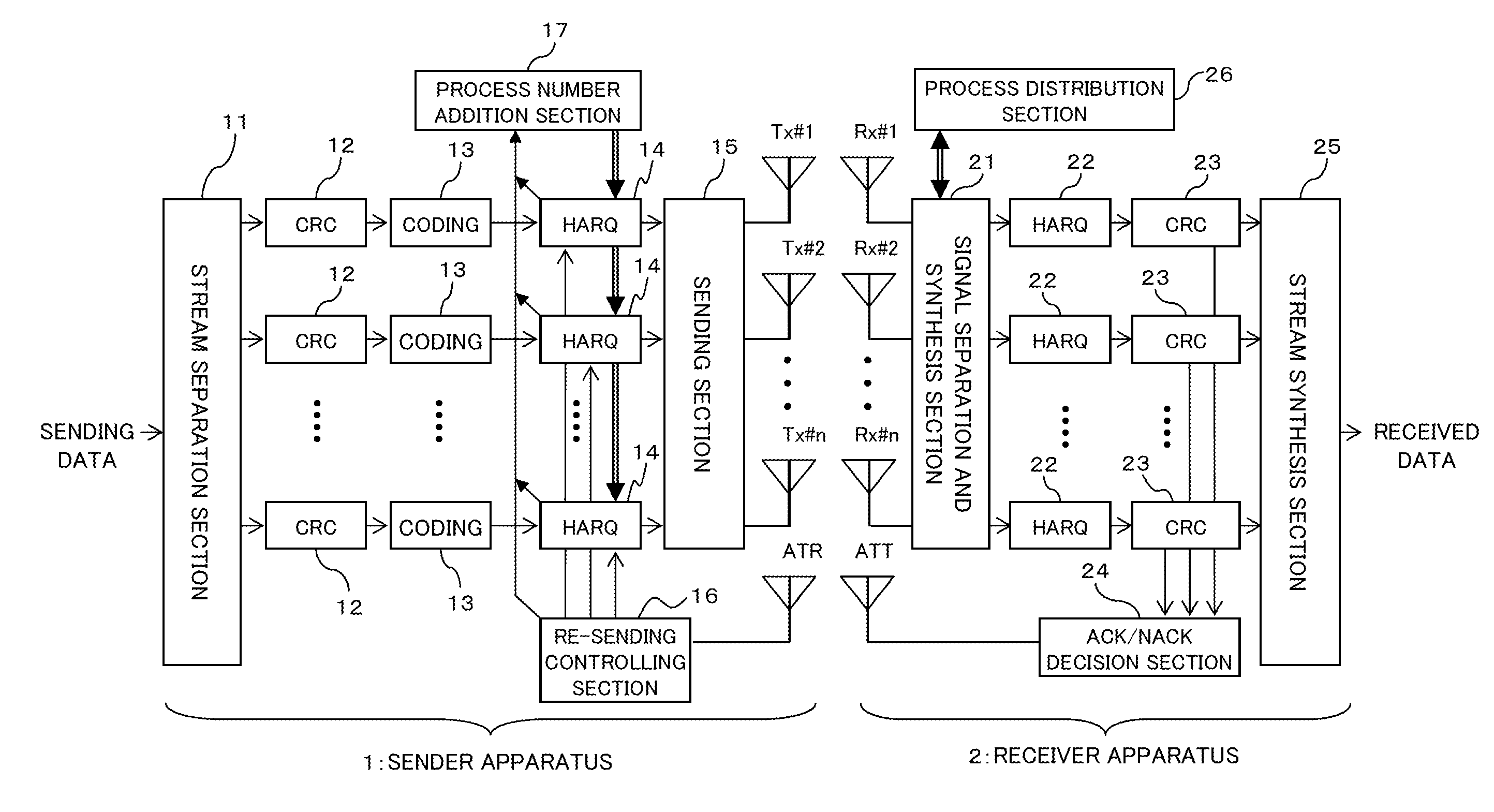
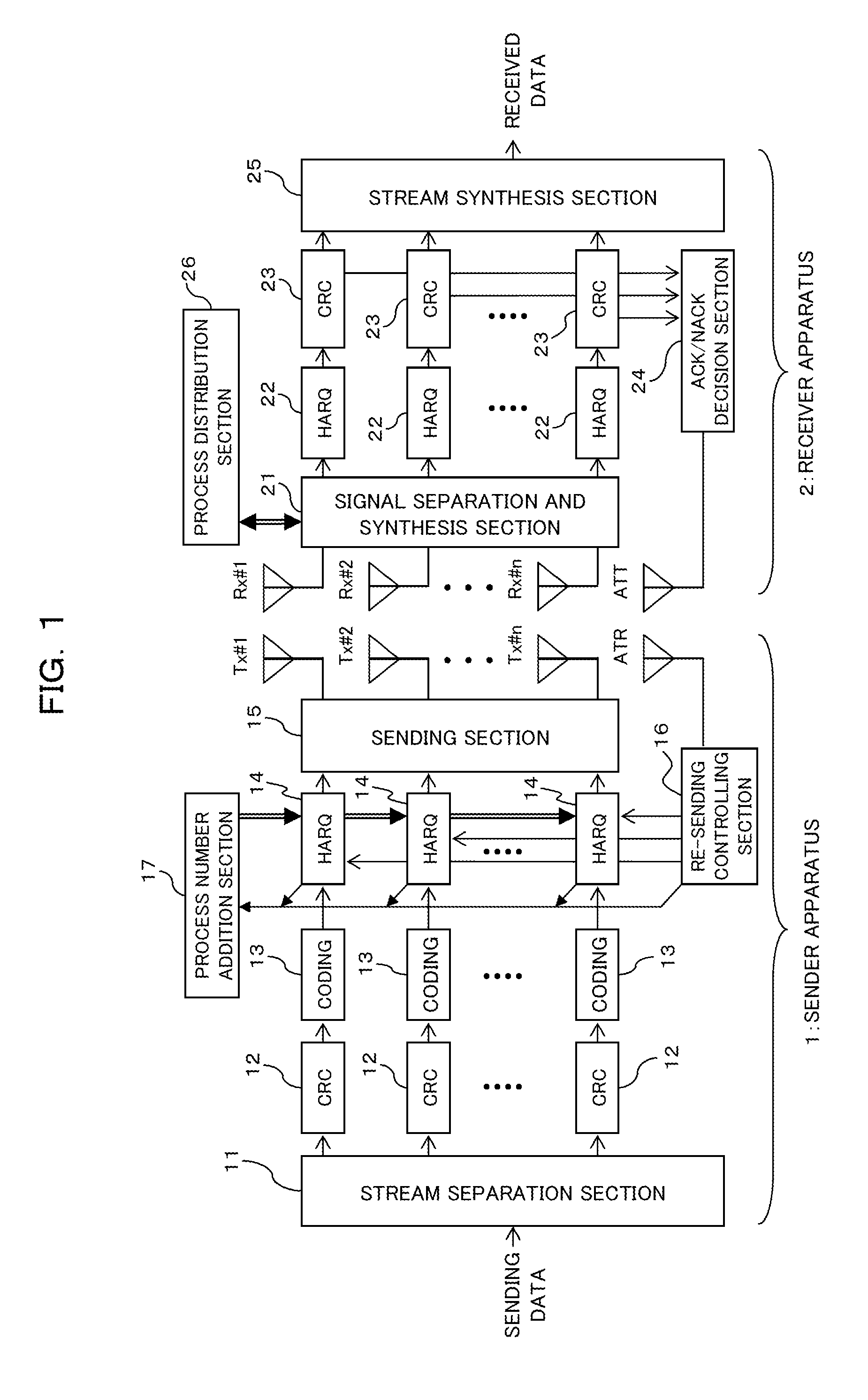
[0121]FIG. 1 is a block diagram depicting a configuration of a MIMO transmission system according to a first embodiment of the present invention, and the MIMO transmission system depicted in FIG. 1 includes at least one sender apparatus 1 having a plurality of sending antennas (antenna systems) Tx#1, Tx#2, . . . and Tx#n and at least one receiver apparatus 2 having a plurality of receiving antennas (antenna systems) Rx#1, Rx#2, . . . and Rx#n. It is to be noted that the sender apparatus 1 can be applied, for example, as a sending system of a base station apparatus and the receiver apparatus 2 can be applied as a receiving system of a mobile station apparatus. Further, while the number of sending antennas and the number of receiving antennas are equal to each other (n) in the present embodiment, the numbers maybe different from each other.

[0122]Then, taking notice of essential part of the sender apparatus 1, the sender apparatus 1 includes, for ...

second embodiment

[B] Description of Second Embodiment

[0170]FIG. 9 is a block diagram depicting a configuration of a MIMO transmission system according to a second embodiment of the present invention and corresponding to FIG. 2. The MIMO transmission system (sender apparatus 1 and receiver apparatus 2) depicted in FIG. 9 is different in comparison with the configuration depicted in FIGS. 1 and 2 in that it includes a process number addition section 17A and a process distribution section 26A in place of the process number addition section 17 and the process distribution section 26 described hereinabove. It is to be noted that the configuration of the other part is same as or similar to that described hereinabove with reference to FIGS. 1 and 2, and in FIG. 9, some of the components of the sender apparatus 1 (stream separation section 11, CRC calculation section 12 and coding section 13) and some of the components of the receiver apparatus 2 (CRC calculation section 22 and stream synthesis section 25) ...

third embodiment

[C] Description of Third Embodiment

[0200]The first and second embodiments described above demonstrate that, by setting an addition method of a process number such that a process number may not be competitive between antenna system, also when the transmission mode changes over from the MIMO multiplex transmission to non-MIMO multiplex transmission, correct synthesis of processes can be achieved and transmission of streams can be continued without interruption while preventing re-sending in error of a process. However, the present embodiment demonstrates a technique of continuing communication without interruption of stream transmission also in conventional PARC or pre-coding wherein a process number is added to a transmission stream independently for each antenna system.

[0201]In the present embodiment, attention is paid to the fact that, originally upon occurrence of a transmission mode changeover, re-sending in error is caused by the fact that a process remains in an antenna system ...


PUM


Abstract

A transmission controlling method for a wireless communication system wherein a plurality of data blocks can be transmitted from a sender apparatus having a plurality of sending antennas to a receiver apparatus, the transmission controlling method including on the sender apparatus, sending process information which prevent plurality of data blocks from competing to the receiver apparatus with a control channel; and on the receiver apparatus, combining, based on the process information, the data block received already and a re-sent data block.

Description

CROSS-REFERENCE TO RELATED APPLICATION(S)[0001]This application is a continuation of U.S. application Ser. No. 12 / 424,642, filed Apr. 16, 2009, now pending, which is a continuation of International Application No. PCT / JP2006 / 321552, filed on Oct. 27, 2006 in Japan, the entire contents of each are herein wholly incorporated by reference.TECHNICAL FIELD[0002]The present invention relates to a transmission controlling method, a sender apparatus and a receiver apparatus for a wireless communication system, and particularly to a technique suitable for use with a re-sending controlling technique in MIMO (Multi Input Multi Output) transmission.BACKGROUND ART[0003]While, regarding a mobile communication system such as a portable telephone system, a service of the third generation method according to a CDMA (Code Division Multiple Access) method has been started already, investigations of a next generation mobile communication system capable of implementing higher-speed communication on the ...

Claims


Application Information

Patent Timeline
Patent Type & Authority Applications(United States)
IPC IPC(8): H04L27/00H04J99/00
CPCH04B7/0689H04J15/00H04L1/06H04L1/1845H04L1/1812H04L1/1816H04L1/1822H04L1/1671H04J99/00H04B7/0413H04W8/00H04W72/00H04W88/02H04W72/20
Inventor OHTA, YOSHIAKIOBUCHI, KAZUHISAKAWABATA, KAZUOKAWASAKI, YOSHIHIROTAJIMA, YOSHIHARUFURUKAWA, HIDETO
Owner FUJITSU LTD
Why Eureka
Try Eureka