Optical Counter-Phase System And Method Of RF Interference Cancellation

a counter-phase system and optical technology, applied in the field of optical counter-phase systems and methods of interference cancellation, can solve the problems of time delays attainable with modem optical devices, unattainable with current state-of-the-art electronic devices, etc., and achieve the effect of reducing the transmitted signal and increasing the dynamic range of the receiver

Active Publication Date: 2012-10-04
THE TRUSTEES FOR PRINCETON UNIV
View PDF6 Cites 75 Cited by
  • Summary
  • Abstract
  • Description
  • Claims
  • Application Information

AI Technical Summary

Benefits of technology

[0009]In a preferred embodiment, the present invention is a system and method for cancellation of RF interference in the optical domain. The system and method utilize two electrooptic modulators biased for parallel counter-phase modulation. In a preferred embodiment, interferometric electrooptic modulators are used, and more specifically, Mach-Zehnder electro-optic modulators are used. The method of signal subtraction may be referred to as incoherent optical subtraction, since two independent laser sources serve as the optical carrier waves. The system has produced the broadband cancellation result while simultaneously recovering a 50 dBm signal which was initially “buried” under the broadband interference. The cancellation depths achieved by the system are due to the accurate channel tracking and precise time delays attainable with modem optical devices—unattainable with current state-of-the-art electronic devices. The system is useful in the context of wireless radio communications because it can increase the dynamic range of a receiver by allowing it to receive weaker signals, even when a much stronger signal is being transmitted in close proximity. For those cases in which the transmitted signal is especially strong and may otherwise saturate the receiver, the system provides a benefit by reducing the transmitted signal significantly.

Problems solved by technology

The cancellation depths achieved by the system are due to the accurate channel tracking and precise time delays attainable with modem optical devices—unattainable with current state-of-the-art electronic devices.

Method used


Image

  • Optical Counter-Phase System And Method Of RF Interference Cancellation
  • Optical Counter-Phase System And Method Of RF Interference Cancellation
  • Optical Counter-Phase System And Method Of RF Interference Cancellation

Examples


Embodiment Construction

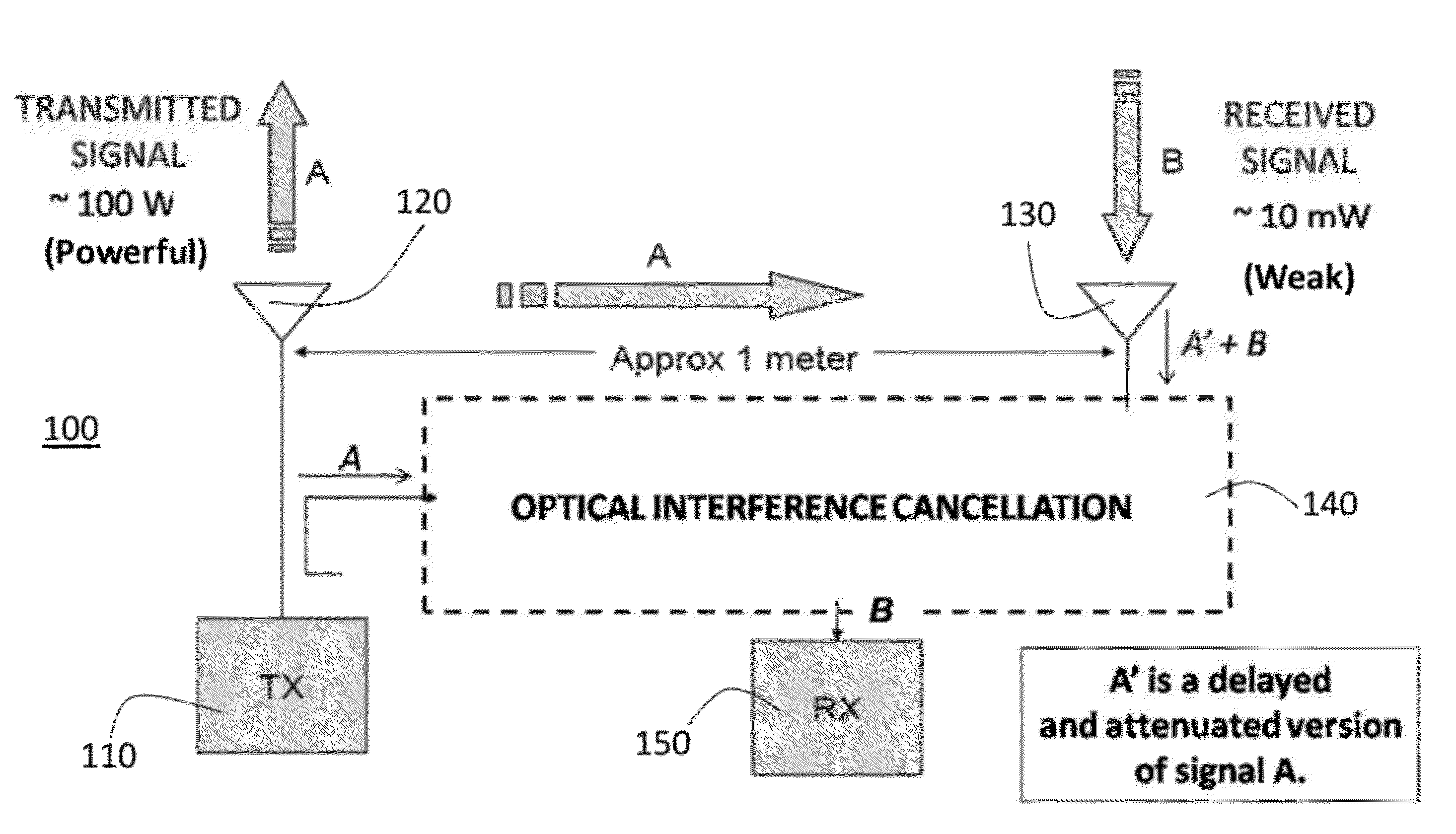
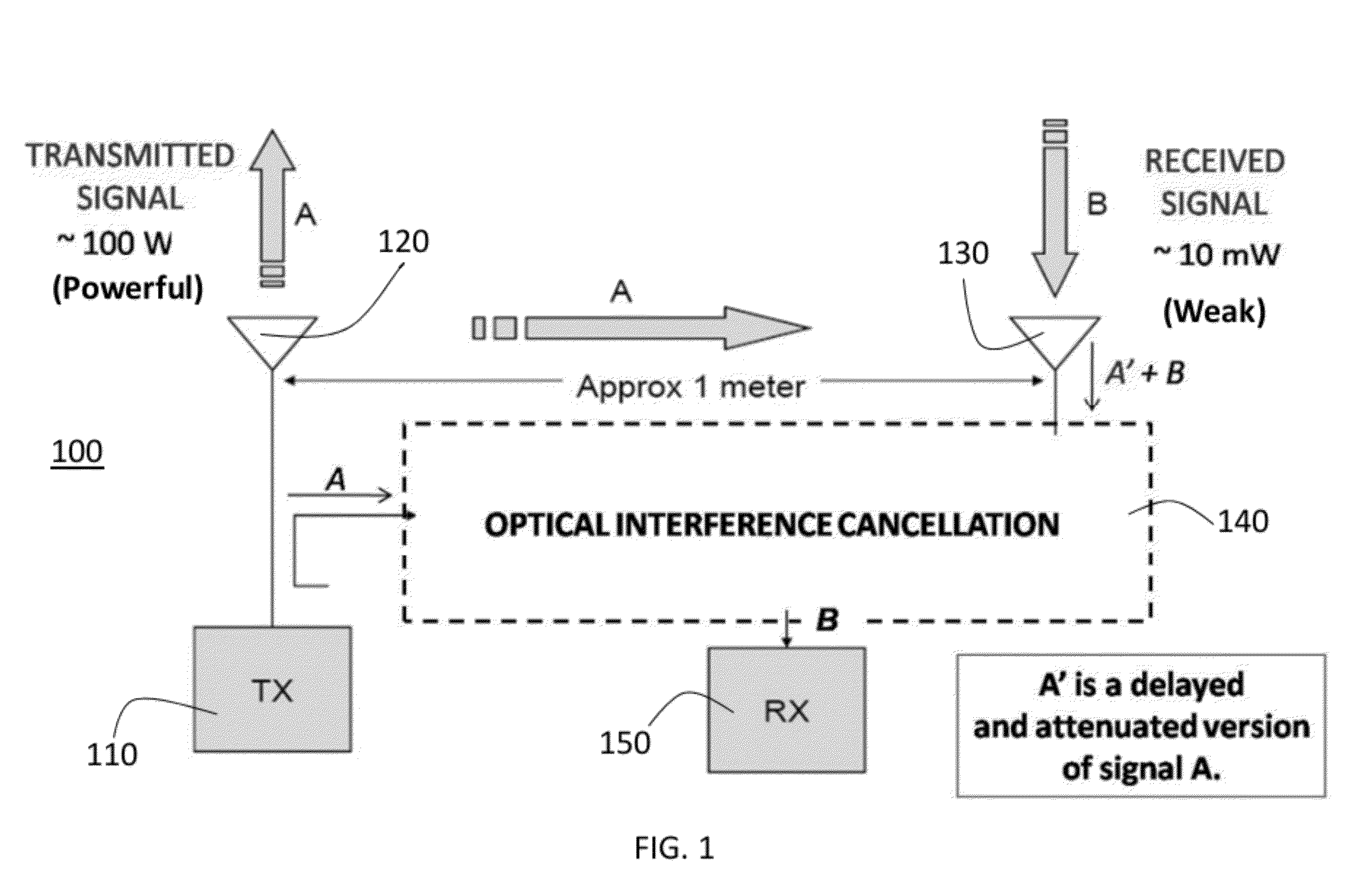
[0027]The present invention employs new systems and methods of optical processing to address problems associated with interfering signals. The general problem is described with reference to system 100 shown in FIG. 1. A transmitting antenna 120, which is connected to a transmitter 110, and receiving antenna 130 are separated by approximately 1 m. The transmitting antenna 120 emits RF radiation whose power is of the order of 100 W, while the power of the received signal (measured at the output of the receiving antenna 130) is of the order of 1 W. The received signal is comprised of both a desired signal and a delayed-and-attenuated replica of the transmitted signal. From the standpoint of the receiver 150, one may consider the transmitted signal to be additive noise which undesirably combines with the desired signal.

[0028]To address this problem, a preferred embodiment of the present invention is an optical interference cancellation system 140 and method that accepts a received signa...


PUM

PropertyMeasurementUnit
poweraaaaaaaaaa
poweraaaaaaaaaa
wavelengthsaaaaaaaaaa

Abstract

A system and method for cancellation of RF interference in the optical domain. The system and method utilize two Mach-Zehnder electrooptic modulators biased for parallel counter-phase modulation. The method of signal subtraction is referred to as incoherent optical subtraction, since two independent laser sources serve as the optical carrier waves. The system has produced the broadband cancellation result while simultaneously recovering a 50 dBm signal which was initially “buried” under the broadband interference. The cancellation depths achieved by the system are due to the accurate channel tracking and precise time delays attainable with modern optical devices—unattainable with state-of-the-art electronic devices at the time of this writing.

Description

CROSS-REFERENCE TO RELATED APPLICATIONS[0001]The present application claims the benefit of the filing date of U.S. Provisional Patent Application Ser. No. 61 / 198,336 filed by the present inventors on Nov. 5, 2008.[0002]The aforementioned provisional patent application is hereby incorporated by reference in its entirety.STATEMENT REGARDING FEDERALLY SPONSORED RESEARCH OR DEVELOPMENT[0003]This invention was made with government support under Prime Contract W911NF-07-D-0001 (Subcontract TCN: 08-004) awarded by the Department of the Army. The government has certain rights in the invention.BACKGROUND OF THE INVENTION[0004]1. Field of the Invention[0005]The present invention relates to systems and methods for interference cancellation, and more specifically, the use of optical techniques in systems and methods for interference cancellation.[0006]2. Brief Description of the Related Art[0007]Radio-frequency (RF) and microwave signals are commonly employed in wireless communications due to t...

Claims


Application Information

Patent Timeline
Patent Type & Authority Applications(United States)
IPC IPC(8): G02F1/035
CPCG02F2/002H04B1/525
Inventor SUAREZ, JOHNKRAVTSOV, KONSTANTINPRUCNAL, PAUL R.
Owner THE TRUSTEES FOR PRINCETON UNIV
Why Eureka
Try Eureka