Round cutting insert with reverse Anti-rotation feature

a technology of anti-rotation and inserts, which is applied in the field of cutting inserts, can solve the problems of affecting the quality of the cut on the workpiece, affecting the quality of the cut, so as to achieve the effect of preventing the rotation of the inser

Active Publication Date: 2012-10-04
KENNAMETAL INC
View PDF3 Cites 42 Cited by
  • Summary
  • Abstract
  • Description
  • Claims
  • Application Information

AI Technical Summary

Benefits of technology

[0007]In another aspect, a cutting tool assembly comprises a tool body having an insert receiving pocket with a projection; and an insert received in the insert receiving pocket, the insert having a first portion having a first outer surface that terminates generally outwardly in a first cutting edge and terminates generally inwardly in a first inner edge; a first inner surface extending generally inwardly from the first inner edge toward a non-cylindrical opening that extends axially through the cutting insert; a plurality of first dimples formed in the first inner surface between the first inner edge and the opening; and a generally circular side surface that extends between the first outer surface and the second outer surface, wherein one of the plurality of first dimples cooperates with the projection of the insert receiving pocket to prevent rotation of the insert when mounted in the insert receiving pocket.

Problems solved by technology

During a cutting operation, such inserts often experience not only compressive and vibratory forces, but some amount of torque due to the angle between the cutting edges of the inserts and the workpiece.
If the clamping screw should become sufficiently loosened, it can vibrate within the surrounding pocket severely enough to become chipped or cracked not only ruining the insert, but also jeopardizing the quality of the cut on the workpiece.
Although such an anti-rotation feature is effective to prevent rotation of the round insert in its respective pocket, such an anti-rotation feature is difficult to manufacture, thereby increasing the cost of both the cutting tool and round insert.

Method used


Image

  • Round cutting insert with reverse Anti-rotation feature
  • Round cutting insert with reverse Anti-rotation feature
  • Round cutting insert with reverse Anti-rotation feature

Examples


Embodiment Construction

[0028]Below are illustrations and explanations for a method for manufacturing an insert pocket of a tool holder. However, it is noted that the fastener may be configured to suit the specific application and is not limited only to the example in the illustrations.

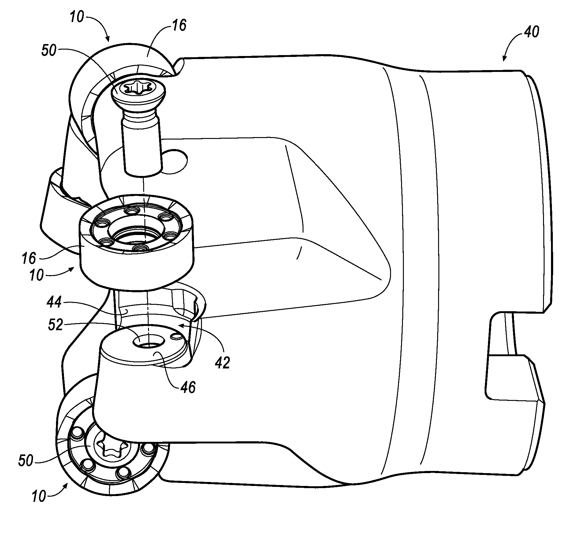
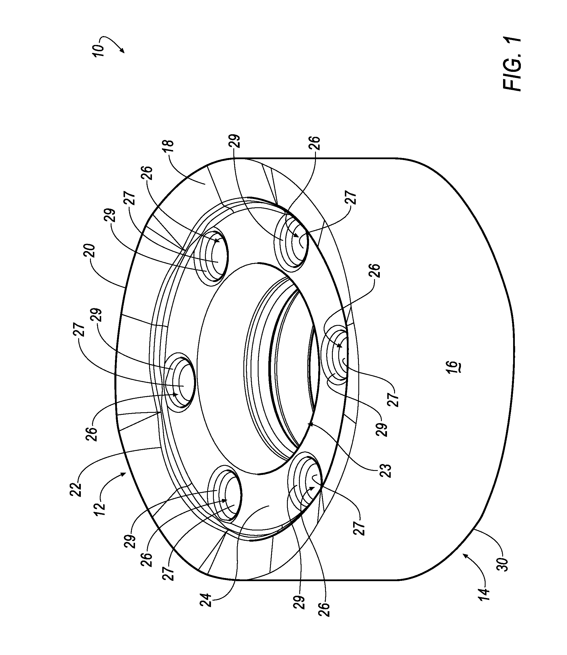
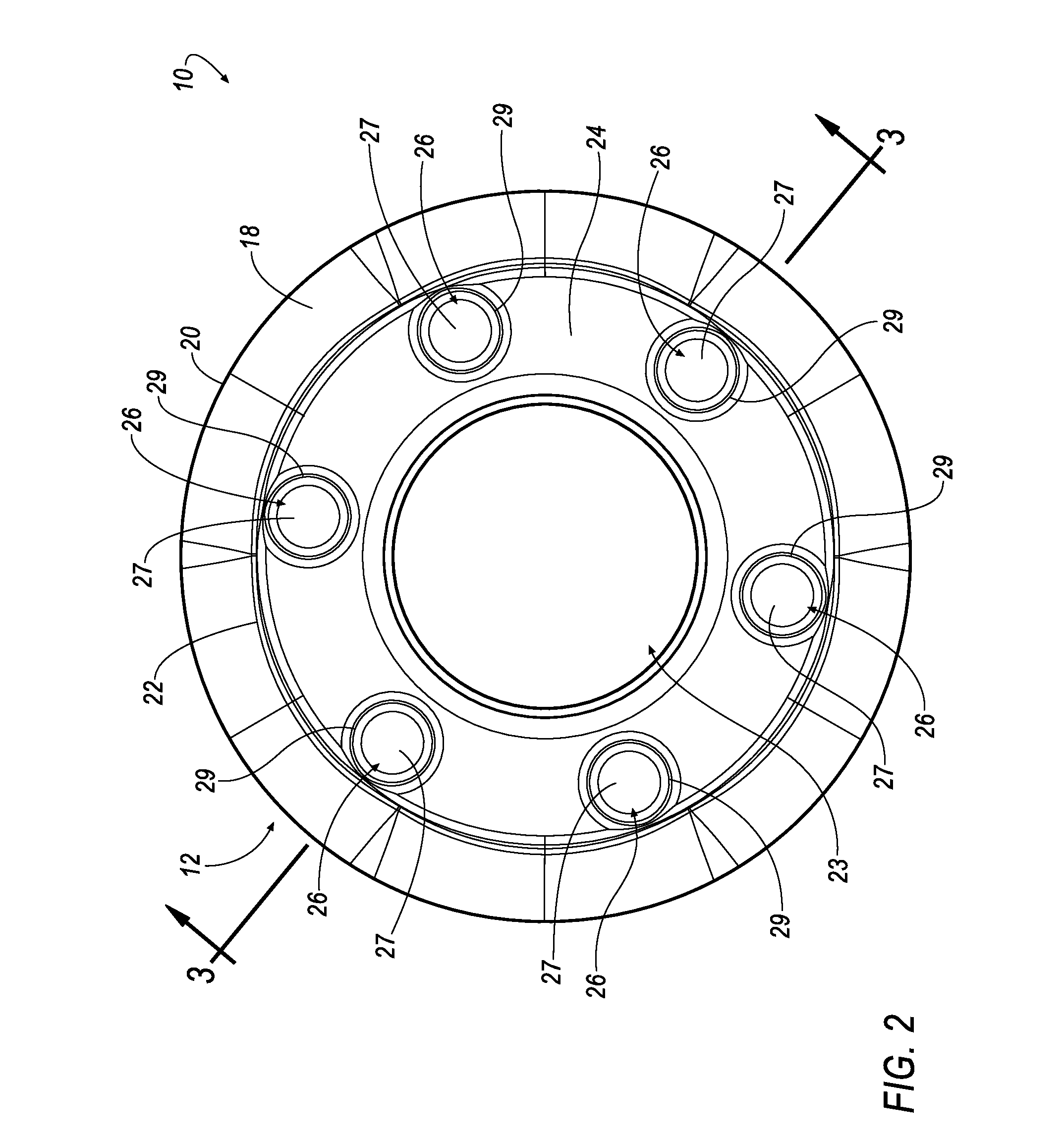
[0029]Referring to FIGS. 1 and 2, wherein like reference characters represent like elements, a cutting insert 10 is shown according to an embodiment of the invention. The cutting insert 10 includes a first or top portion 12 (see generally FIGS. 1, 2, 3 and 5) and a second or bottom portion 14 (see generally FIGS. 3, 4 and 5), and a generally circular side portion 16 that extends between the first portion 12 and the second portion 14. Thus, it will be appreciated that the cutting insert 10 is a generally round cutting insert for positioning in a tool body for performing a cutting operation on a workpiece (not shown).

[0030]As shown in FIGS. 1 and 2, the cutting insert 10 includes a first outer surface 18 that terminates in a g...


PUM


Abstract

A round cutting insert with a reverse anti-rotation feature that can be manufactured easily and inexpensively is disclosed. The round cutting insert includes a plurality of dimples formed on a first surface and another plurality of dimples formed on a second, opposing surface. The round insert is reversible and indexable. The round cutting insert is removable received in an insert receiving pocket in a tool body. The insert receiving pocket includes a single projection that is capable of being received in one of the plurality of dimples. The cooperation between the projection and one of the plurality of dimples prevents rotation of the round cutting insert when mounted in the insert receiving pocket. The plurality of dimples and the projection can be any desirable complimentary shape, such as a slot, a V-shape, a wagon wheel, a sports wheel, a pyramid, and the like.

Description

BACKGROUND OF THE INVENTION[0001]The invention relates generally to cutting inserts and, more particularly, relates to round cutting inserts having a reverse anti-rotation feature for preventing rotation of the round cutting insert mounted onto the body of a cutting tool.[0002]The inserts used in tools such as, for example, milling cutters are mounted in complementarily-shaped pockets spaced around the periphery of the tool body. The inserts are typically secured within their respective pockets by clamping screws inserted through a hole provided in the center of the insert. During a cutting operation, such inserts often experience not only compressive and vibratory forces, but some amount of torque due to the angle between the cutting edges of the inserts and the workpiece. For cutting inserts of non-round shapes, such torque does not result in the rotation of the insert due to the interference-type fit between the angled sidewalls of such inserts and the complementarily-shaped wall...

Claims


Application Information

Patent Timeline
Patent Type & Authority Applications(United States)
IPC IPC(8): B23C5/22B23C5/02
CPCY10T407/1964B23C2200/165B23B27/1622Y10T407/1936B23C2200/045B23C2210/163B23C2200/168Y10T407/23Y10T407/1924B23C2210/168Y10T407/20B23C5/2221B23C2200/206B23C5/2213
Inventor MORRISON, LEWIS RAYMYLAVARAM NIKHILESH, KUMAR REDDYMALI, SURESH
Owner KENNAMETAL INC
Why Eureka
Try Eureka