Chamfering device and gear processing machine provided therewith

Active Publication Date: 2012-10-04
MITSUBISHI HEAVY IND MACHINE TOOL CO LTD
View PDF1 Cites 4 Cited by
  • Summary
  • Abstract
  • Description
  • Claims
  • Application Information

AI Technical Summary

Benefits of technology

[0030]According to the chamfering device concerned with the present invention, the feed amount of the chamfering cutter and the feed amount of the deburring cutter with respect to the workpiece are rendered nearly equal over the diameter range of the workpiece to be processable by the chamfering cutter and the deburring cutter, from the maximum diameter to the minimum diameter. As a result, the chamfering cutter and the deburring cutter can be positioned by the single feed block. Thus, the position adjustment of the respective cutters with respect to the workpiece can be made easily by the simple structure. Moreover, the device can be downsized.
[0031]According to the chamfering device concerned with the present invention, the feed block is composed of the two feed blocks, and the axial feed mechanism capable of axially feeding one of the feed blocks toward the workpiece, and has the shaft disposed to be capable of supporting the one feed block on the other feed block. Thus, the position adjustment of the chamfering cutter and the deburring cutter with respect to the workpiece can be made easily by the simple structure.
[0032]The chamfering device according to the present invention further comprises the restraint means for restraining the swing of the one feed block by the shaft. Thus, the chamfering cutter and the deburring cutter can be arranged at such locations that the distance between the axis of the chamfering cutter and the workpiece and the distance between the axis of the deburring cutter and the workpiece equal each other. Thus, the position adjust

Problems solved by technology

That is, the chamfering cutter is pressed against a location of th

Method used


Image

  • Chamfering device and gear processing machine provided therewith
  • Chamfering device and gear processing machine provided therewith
  • Chamfering device and gear processing machine provided therewith

Examples


embodiment 1

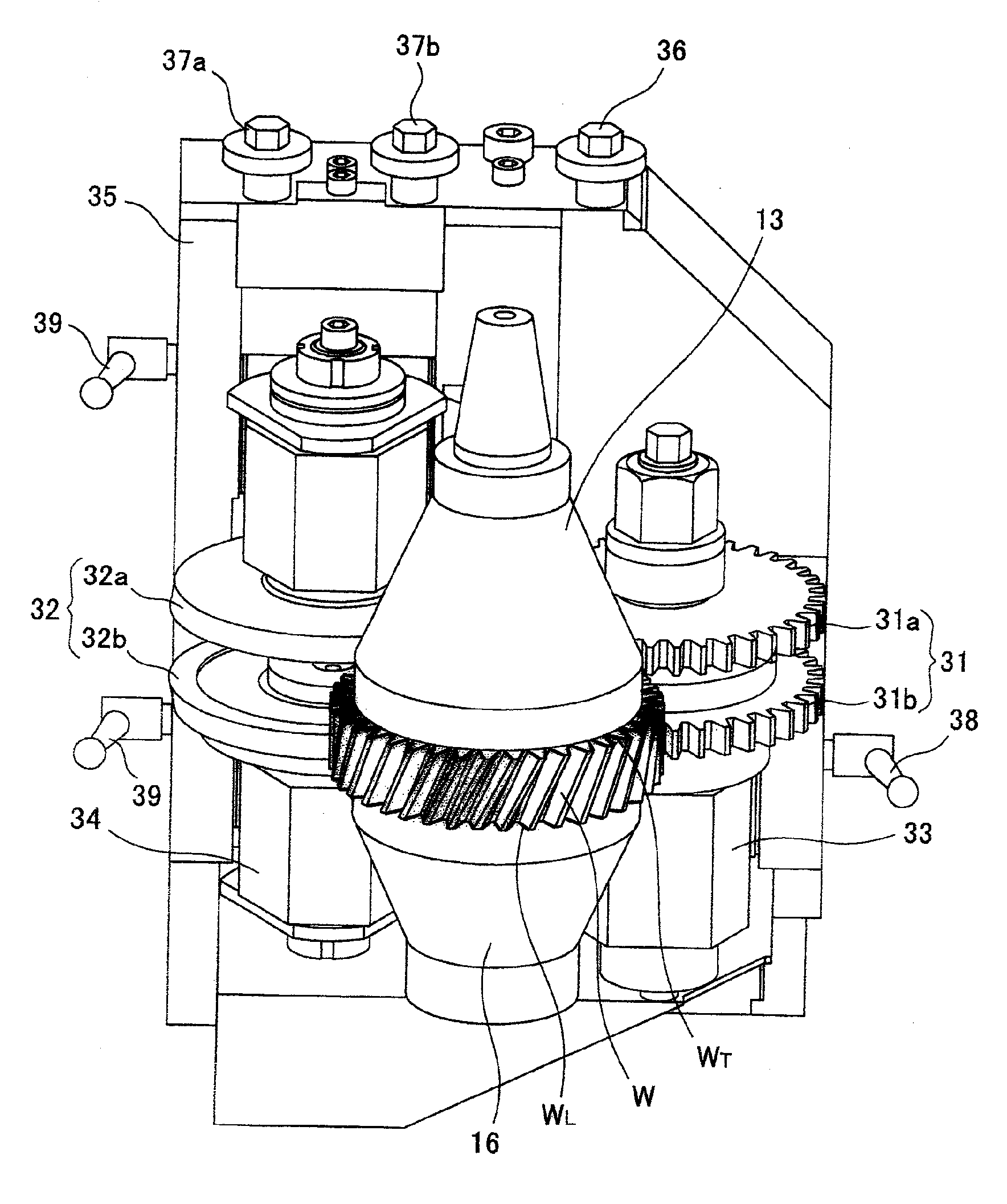
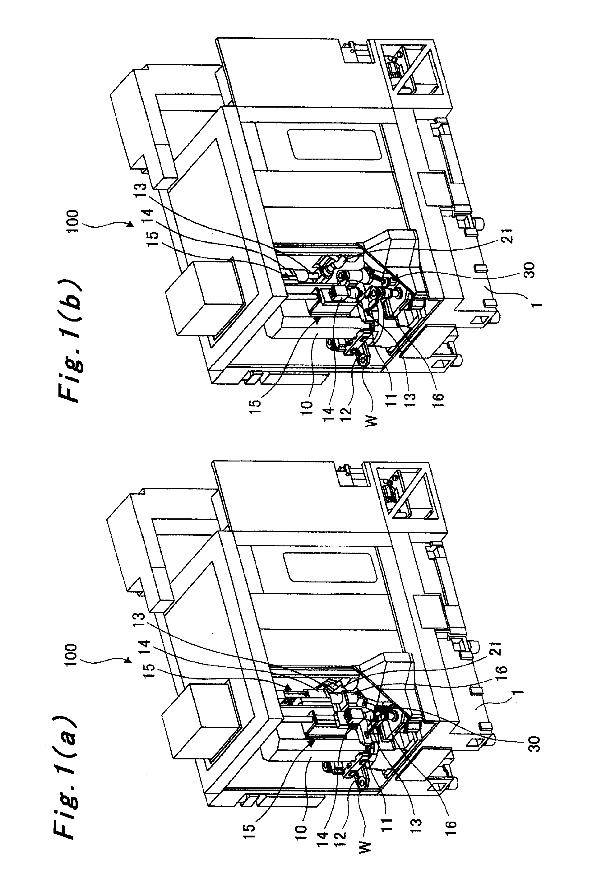
[0044]The gear cutting machine according to the first embodiment of the present invention will be concretely described using FIGS. 1(a), 1(b) to FIGS. 7(a) to 7(e). In FIG. 4 to FIGS. 6(a), 6(b), the positions of a workpiece, a chamfering cutter, and a deburring cutter when the workpiece to be processed is in the maximum size (maximum diameter) are indicated by solid lines, while the positions of the workpiece, the chamfering cutter, and the deburring cutter when the workpiece to be processed is in the minimum size (minimum diameter) are indicated by dashed dotted lines. In FIG. 5, the state before processing of the workpiece is indicated by dashed double-dotted lines.

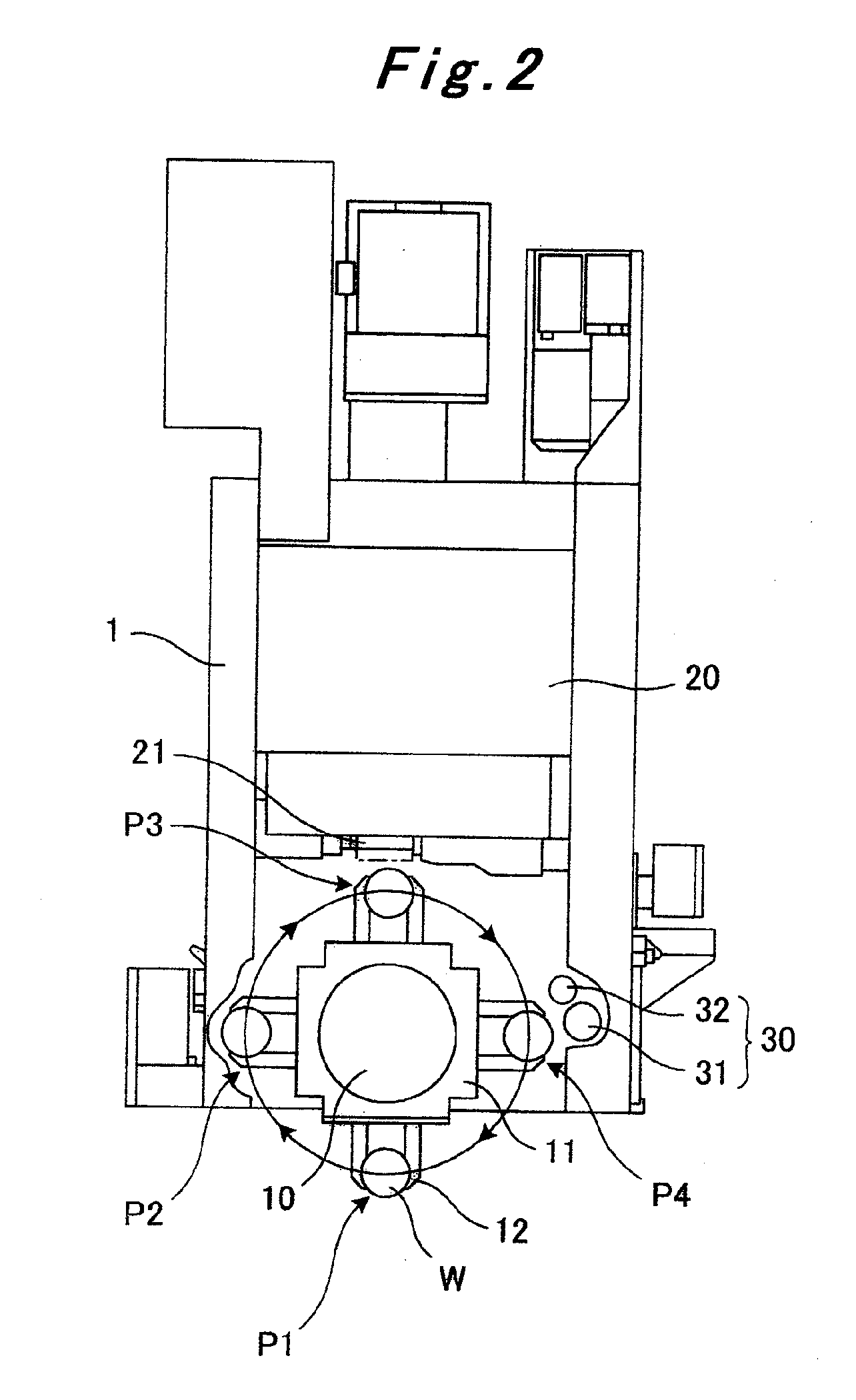
[0045]A gear cutting machine 100 according to the first embodiment of the present invention is a hobbing machine for cutting a gear in a workpiece by use of a hob, as shown in FIGS. 1(a), 1(b) and FIG. 2. This gear cutting machine 100 has a bed 1, a counter column 10 erected on the bed 1, a swing ring (4-station ring l...


PUM

PropertyMeasurementUnit
Diameteraaaaaaaaaa
Elasticityaaaaaaaaaa

Abstract

Position adjustments of a chamfering cutter and a deburring cutter in a chamfering device with respect to a workpiece can be easily carried out. The chamfering device has a chamfering cutter, a deburring cutter which has a diameter different from that of the chamfering cutter; a cutter swing block, a cutter longitudinal feed block, and a base block, which rotatably support the chamfering cutter and the deburring cutter and are capable of subjecting the chamfering cutter and the deburring cuter to position adjustment with respect to the workpiece. The longitudinal feed block can perform single-axis feeding with respect to the workpiece. The chamfering cutter and the deburring cutter are disposed so that the cutting change amount of the chamfering cutter and that of the deburring cutter will be approximately equal to each other throughout the diameter range of the workpiece to be processed.

Description

TECHNICAL FIELD[0001]This invention relates to a chamfering device and a gear processing or cutting machine provided therewith.BACKGROUND ART[0002]After a gear is cut in a workpiece by a hobbing machine or the like, the tooth profile ridge of a gear end face is chamfered (gear chamfering), if necessary. This chamfering function is performed using a chamfering cutter and a deburring cutter (see, for example, Patent Document 1). That is, the chamfering cutter is pressed against a location of the workpiece where the gear is formed, to cause plastic deformation. Burrs, which occur at the edge of the workpiece by this plastic deformation, are cut and removed by the deburring cutter having a disk-shaped blade.[0003]As the chamfering device having the above-mentioned chamfering function, there are a device having respective cutters (a chamfering cutter and a deburring cutter) provided on feed blocks (i.e., a device with a plurality of axial feed mechanisms), and a device having a chamferin...

Claims


Application Information

Patent Timeline
IPC IPC(8): B23F19/10
CPCY10T409/101113B23F19/10B23F19/102Y10T29/5176Y10T409/108586
Inventor MASUO, KOICHITOKAWA, TAKAHIDE
Owner MITSUBISHI HEAVY IND MACHINE TOOL CO LTD
Why Eureka
Try Eureka