Device for Defrosting, Warming and Cooking Using a Circulating Fluid

a technology of circulating fluid and food, which is applied in the field of devices for defrosting, warming and/or cooking food in liquid, can solve the problems of reducing the oxygen level and reducing the chance for aerobic bacteria growth in food

Inactive Publication Date: 2012-10-04
NEFF RAYMOND L +1
View PDF78 Cites 61 Cited by
  • Summary
  • Abstract
  • Description
  • Claims
  • Application Information

AI Technical Summary

Benefits of technology

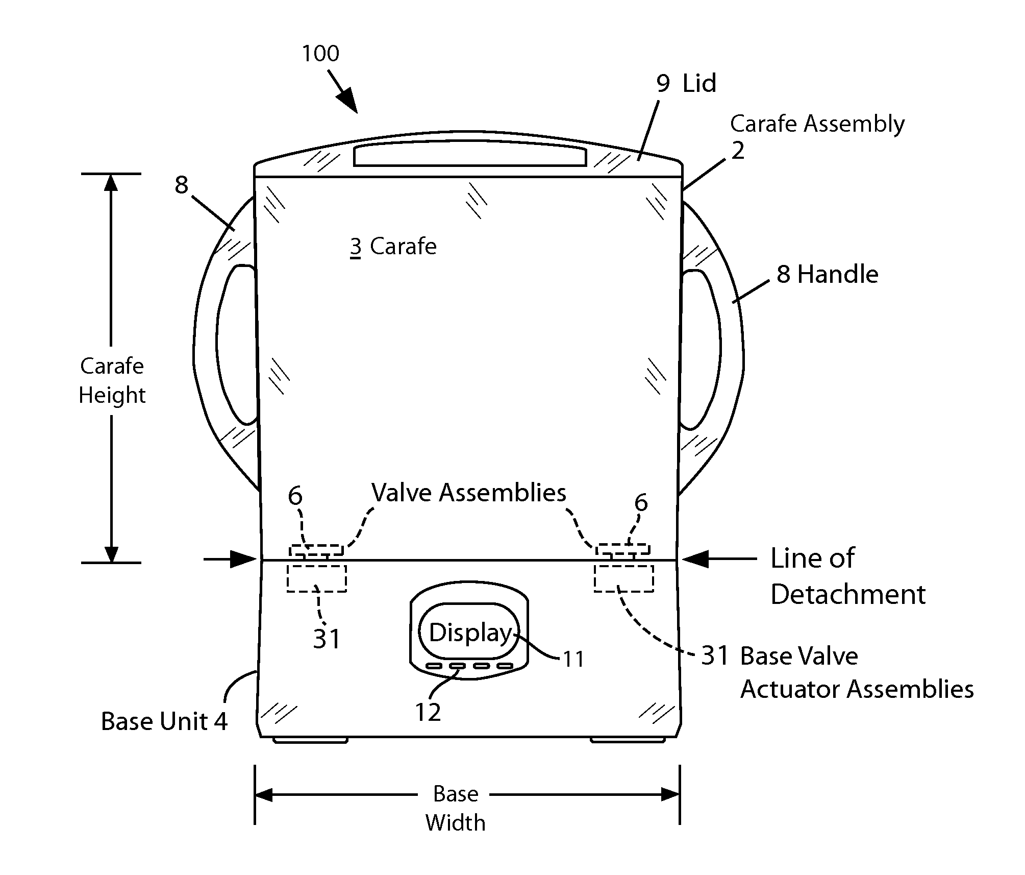
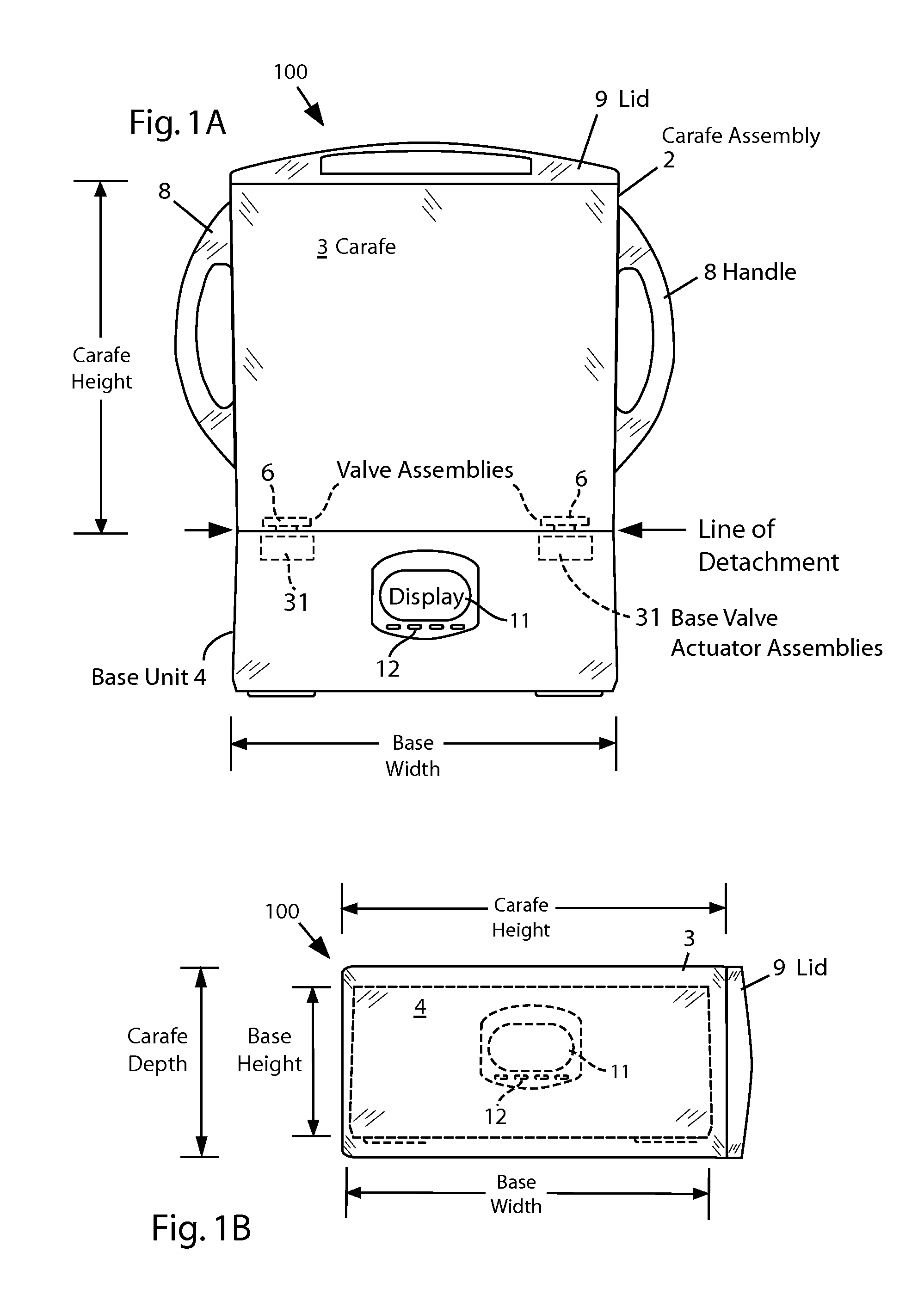
[0015]The present invention comprises a cooking-type device that can defrost, warm and/or cook food items in a temperature controlled circulating liquid such as water. Embodiments of the device are particularly useful for sous vide cooking. An embodiment of the invention includes a liquid-holding vessel (carafe) sized to allow the selected food item to be immersed in the liquid and includes means for operably engaging with the base unit. The liquid can be water or any other n

Problems solved by technology

Reducing the level of oxygen also dramatically decreases

Method used


Image

  • Device for Defrosting, Warming and Cooking Using a Circulating Fluid
  • Device for Defrosting, Warming and Cooking Using a Circulating Fluid
  • Device for Defrosting, Warming and Cooking Using a Circulating Fluid

Examples


first embodiment

[0049]The operation of the base unit 4 will be further discussed with reference to FIG. 5, which is a schematic illustration of selected components of a base unit according to the invention. The major components of the base unit 4 in this embodiment are:[0050]A) Pump 51 and pump relay 51R;[0051]B) Heater assembly 52 and heater relay 52R;[0052]C) Tubing system 56 for fluid flow;[0053]D) Control System Electronics (CSE) Unit 60;[0054]E) Pressure sensors 54;[0055]F) Temperature sensors 55;[0056]G) Valve Actuator Assemblies 31[0057]H) User interface, including:[0058]1) Display 11;[0059]2) Keypad 12.

[0060]The pump 51 and heating assembly 52 are arranged in a serial fluid flow path. The pump 51 and heater assembly 52 can be operated independently through the respective relays. Electrical power to the heater assembly 52 and pump 51 is separately controlled via standard switching devices such as mechanical relays, solid state relays (SSR), or TRIACs. The pump is normally on during operation...

second embodiment

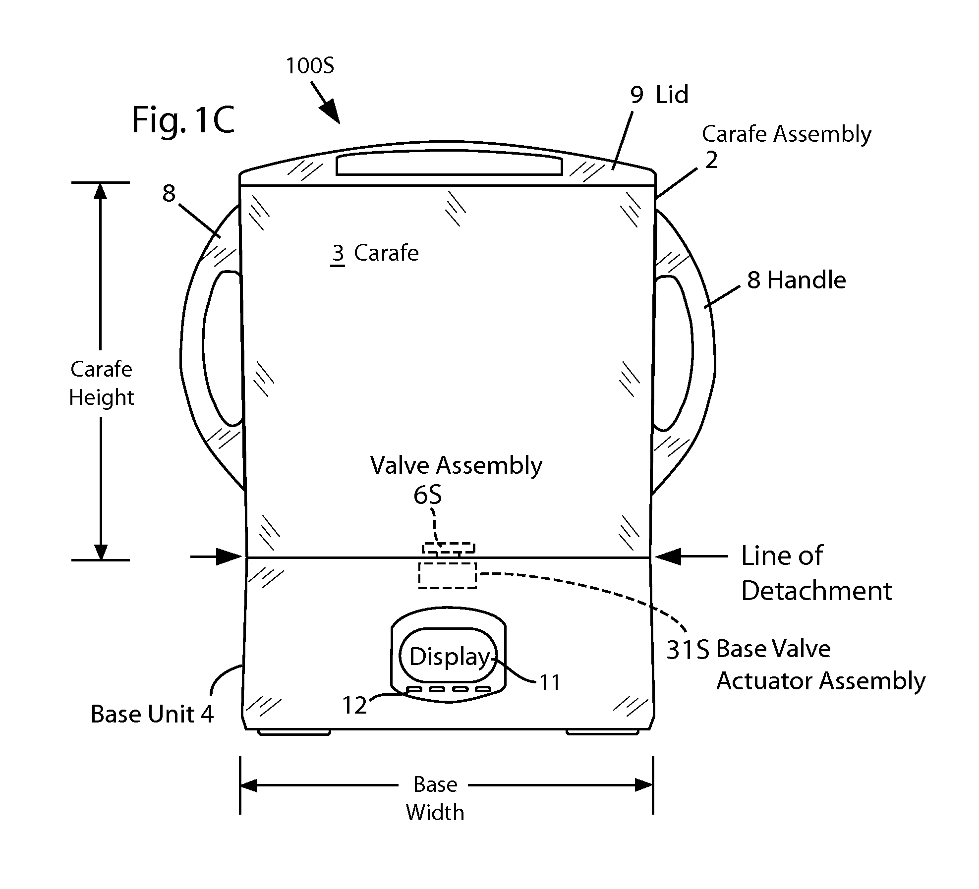
[0075]FIG. 10 is an illustration of a cross section view of valve assembly of FIG. 7 taken along the plane A-A labeled in FIG. 7. This illustration shows that the baffle 71 has a generally circular cross section, as does protruding ring 46.

[0076]FIG. 11 is an illustration of a top view of the mating surface 45P portion of the carafe bottom which is under the piston (not shown) used with the embodiment of valve assembly 6S of FIG. 7. The shaft of piston 41 passes through aperture 74. The inner ring of holes 72 are disposed to conduct flow from inside the baffle 71 when the valve is open, i.e., when the piston 41 is pushed up from the mating surface 45P (as shown in FIG. 9). The outer ring of holes 73 are disposed to conduct return flow outside of the baffle 71 when the valve is open.

[0077]The flow into the carafe is through tube 33A which fits snugly in the circular bottom opening of baffle 71. The valve actuator portion 34 (see FIG. 8) pushes the piston 41 to open the valve in the s...


PUM


Abstract

A device that defrosts, warms and/or cooks items such as food in a temperature controlled circulating liquid is described. Embodiments of the device are particularly useful for sous vide cooking that uses relatively low temperatures and long cooking times. The active components including a pump and heater are placed in a self-contained base unit. When the base unit and the liquid-containing vessel or carafe are engaged, the liquid in the carafe is actively circulated by the pump in the base unit. The liquid is also heated as required as it flows through the base unit. Embodiments of the invention that are designed for the consumer can include an easily detachable, lightweight carafe that can be conveniently filled, emptied and cleaned while detached from the base unit. The detachable carafe can be designed with no electrical components so that it can be immersed in water for cleaning.

Description

RELATED APPLICATION[0001]This application claims the priority date of U.S. Provisional Application No. 61-469868, filed on Mar. 31, 2011. This prior application is incorporated herein by reference in its entirety.FIELD OF THE INVENTION[0002]The present invention relates generally to devices for defrosting, warming and / or cooking food in a liquid and methods for their use. More specifically, the present invention relates to such devices that include means for actively circulating the liquid around the food.BACKGROUND[0003]Although the invention described herein can be used in many ways, a particular method of use is in what is popularly called sous vide cooking. The French term “sous vide” is widely used in English to refer to a method of slowly cooking food in vacuum sealed plastic pouches. The term “sous vide” literally means “under vacuum,” and it is sometimes used in the more literal sense to refer to the process of creating the food-filled vacuum sealed pouches. Accordingly a so...

Claims


Application Information

Patent Timeline
IPC IPC(8): A47J27/10A23L1/01A23L5/10
CPCA23L1/0128A47J27/10A47J27/004A23L5/15A23L5/13A23V2002/00
Inventor NEFF, RAYMOND L.MORAN, RICHARD P.
Owner NEFF RAYMOND L
Why Eureka
Try Eureka