Connector to be electrically connected to connecting target and to substrate

a technology of connecting target and substrate, applied in the direction of coupling device connection, two-part coupling device, electrical apparatus, etc., to achieve the effect of improving the reliability of electrical connection

Inactive Publication Date: 2012-10-04
FUJITSU COMPONENENT LTD
View PDF5 Cites 25 Cited by
  • Summary
  • Abstract
  • Description
  • Claims
  • Application Information

AI Technical Summary

Benefits of technology

[0017]The present invention is made in light of the above problems, and provides a connector capable of improving the reliability in an electrical connection and being connected to a substrate by press-fit.

Problems solved by technology

Therefore, it may become difficult to maintain the pushing force of the second contact portion toward the pad to the predetermined value and so that it is required to improve the reliability in an electrical connection of the connector.

Method used


Image

  • Connector to be electrically connected to connecting target and to substrate
  • Connector to be electrically connected to connecting target and to substrate
  • Connector to be electrically connected to connecting target and to substrate

Examples


first embodiment

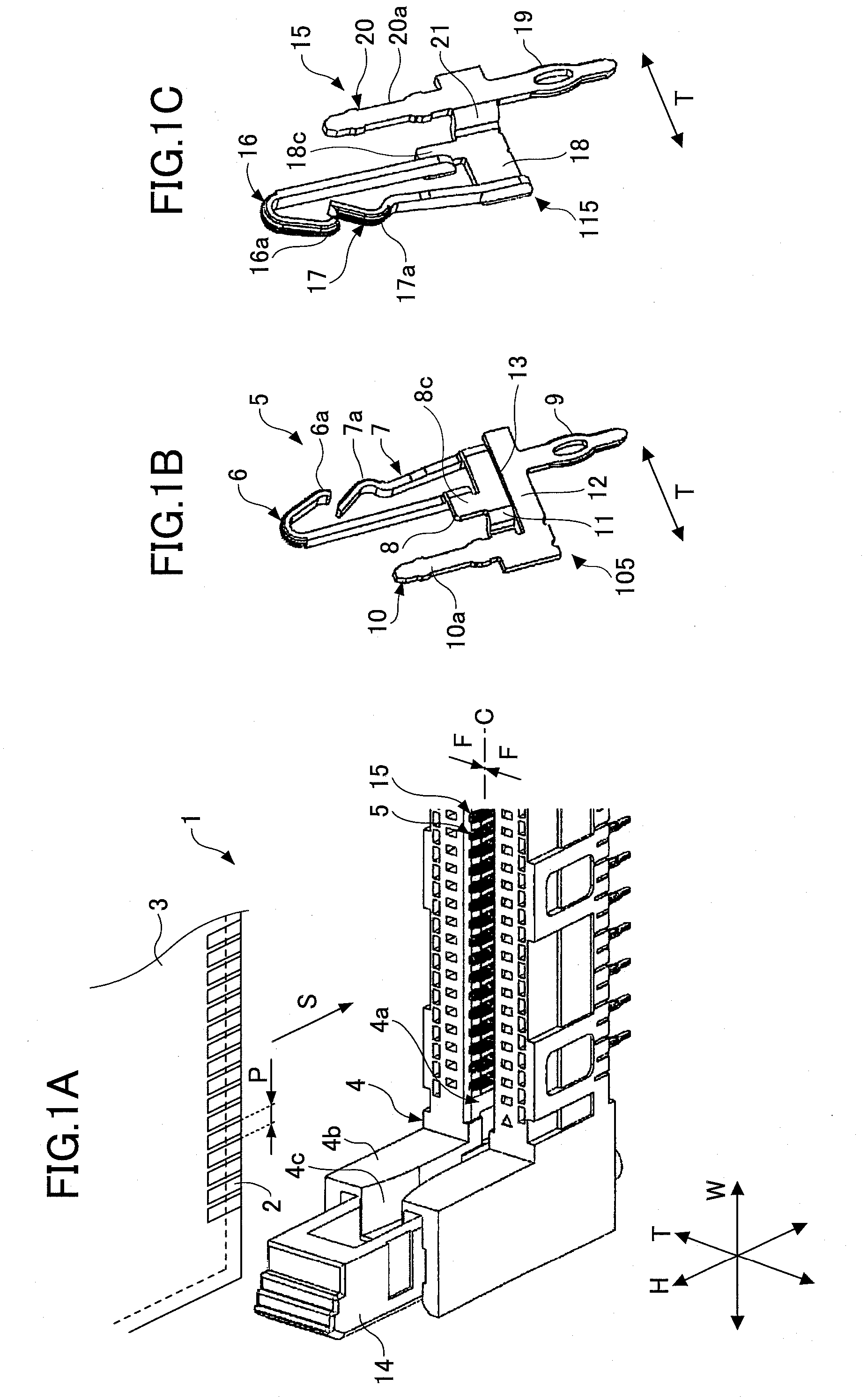
[0054]FIG. 1A is a perspective view showing a connector 1 of a first embodiment and a card edge connector 3 (connecting target).

[0055]In this embodiment, the connector 1 is intended to electrically connect the card edge connector 3 and a substrate 30 (not shown in FIG. 1A, see FIG. 13) provided with plural through holes TH (concave portions).

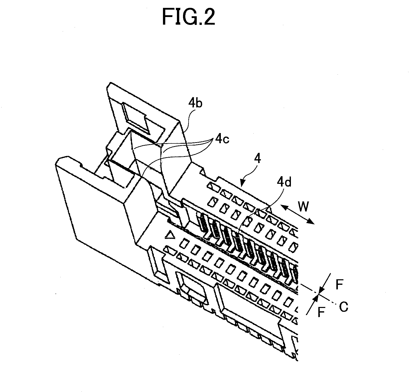
[0056]The connector 1 includes a housing 4 provided with an opening portion 4a, plural first kind of contacts 5, and plural second kind of contacts 15.

[0057]In this embodiment, the card edge connector 3 includes plural pads 2 (objects to be connected) aligned in a width direction “W” of the housing 4 of the connector 1. In this embodiment, the plural pads 2 are aligned on both surfaces of the card edge connector 3 with a predetermined pitch “P”.

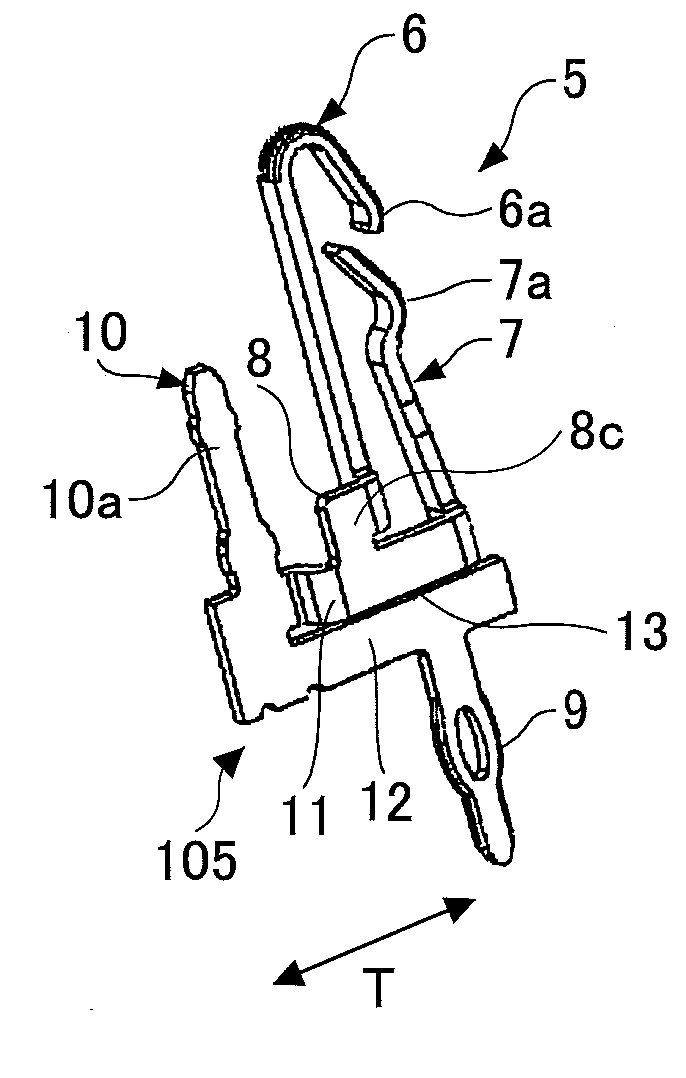
[0058]For the connector 1, the first kind of contacts 5 and the second kind of contacts 15 are held by the housing 4. The first kind of contacts 5 and the second kind of contacts 15 are alternatively alig...

second embodiment

[0150]FIG. 14 is a perspective view of a housing 34 of a connector 31 of a second embodiment. FIG. 15 is a perspective view of the connector 31 including the housing 34, first kind of contacts 35 and second kind of contacts 45 of the second embodiment.

[0151]In this embodiment as well, the connector 31 is intended to electrically connect the card edge connector 3 (see FIG. 1) and the substrate 30 (see FIG. 13) similar to the connector 1 of the first embodiment. The structure of the card edge connector 3 may be similar to that described in the first embodiment.

[0152]The connector 31 includes the housing 34, plural of the first kind of contacts 35, and plural of the second kind of contacts 45.

[0153]FIG. 16 is an enlarged perspective view of the first kind of contact 35. FIG. 17A is a side view, FIG. 17B is a plan view and FIG. 17C is a top view, of the first kind of contact 35.

[0154]The first kind of contact 35 includes a base portion composed of a support portion 38 and a connecting p...


PUM


Abstract

A connector to be electrically connected to a connecting target including plural electrical objects and to a substrate provided with plural concave portions, includes plural contacts, each including a first terminal configured to extend in a first direction to be connected with the object of the connecting target and include a first contact portion and a second contact portion, a second terminal configured to extend in a second direction opposite to the first direction to be fitted in the concave portion of the substrate, and a base portion configured to be provided with a support portion that separately supports the first contact portion and the second contact portion of the first terminal at different positions and separately support the second terminal from the first terminal.

Description

BACKGROUND OF THE INVENTION[0001]1. Field of the Invention[0002]The present invention relates to a connector and more specifically, to a connector used for electrically connecting a home, an office or an industrial electronic device and a substrate or substrates in an electronic device.[0003]2. Description of the Related Art[0004]Patent Document 1, for example, discloses a connector including a power source, a signal line, a ground line, a shield line or the like for connecting a substrate and an electronic device or substrates in an electronic device.[0005]In Patent Document 1, it is disclosed a connector for which a circuit substrate in a form of a card edge connector such as a Dual Inline Memory Module (DIMM) or the like composed of plural Dynamic Random Access Memory (DRAM) mounted on a print substrate, is a connecting target.[0006]For the card edge connector, plural pads are aligned on its surfaces with equal intervals in an alignment direction which is perpendicular to an inse...

Claims


Application Information

Patent Timeline
Patent Type & Authority Applications(United States)
IPC IPC(8): H01R24/60
CPCH01R12/585H01R13/2457H01R12/716
Inventor TAJIRI, HIROSHIMIKI, YASUYUKIKOBAYASHI, MITSURU
Owner FUJITSU COMPONENENT LTD
Why Eureka
Try Eureka