Hydraulic tensioner
a technology of hydraulic tensioner and plunger, which is applied in the direction of belt/chain/gearing, mechanical equipment, belts, etc., can solve the problems of increasing costs and reducing the effect of oil emission performance, reducing the sliding resistance of the plunger, and enhancing the oil emission property of the downstream sid
- Summary
- Abstract
- Description
- Claims
- Application Information
AI Technical Summary
Benefits of technology
Problems solved by technology
Method used
Image
Examples
second embodiment
[0100]the present invention shown in FIGS. 9 and 10 will be described.
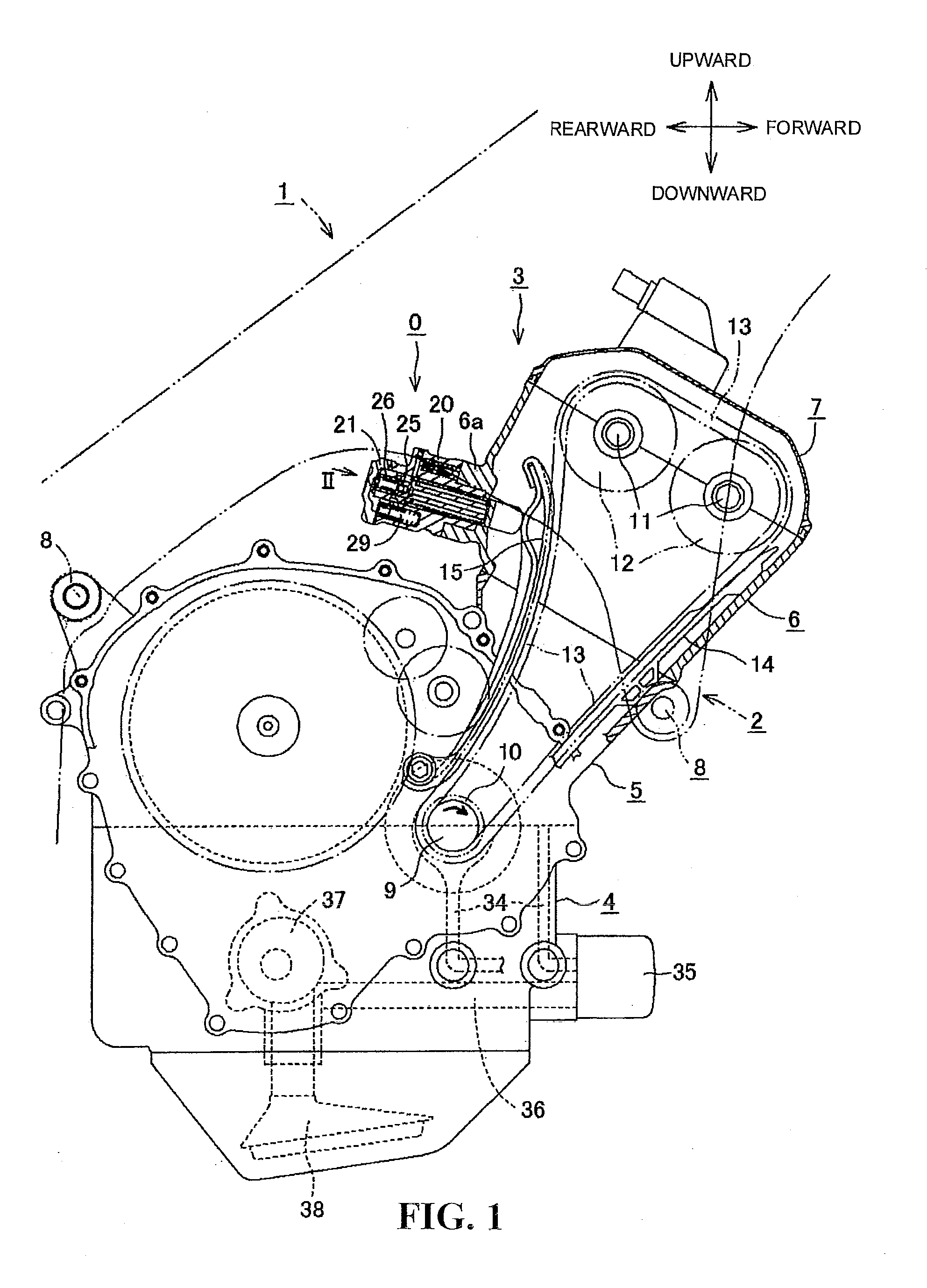
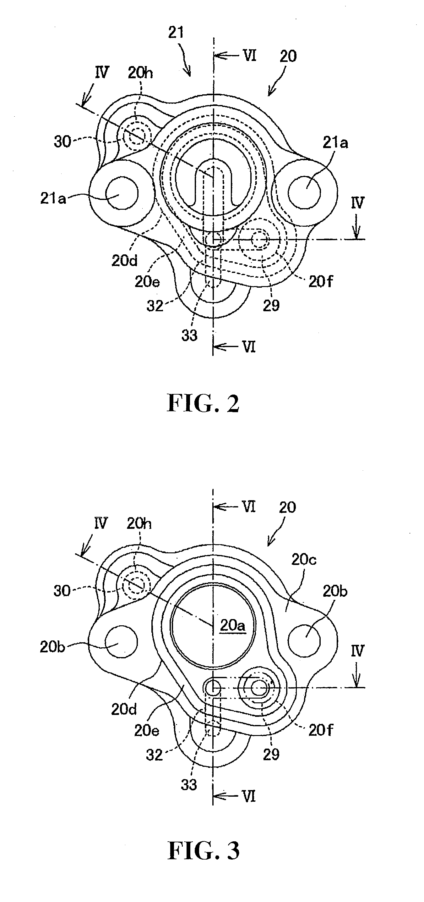
[0101]A pressure maintaining valve 39 is used in place of the pressure maintaining valve 29 shown in FIGS. 1 to 8. In this pressure maintaining valve 39, a pressure maintaining valve port 39f is formed on an outer circumferential portion 39e of a valve head portion 39d of a valve body 39c, and a communication hole 39g is formed in a spring receiver 39a. This communication hole 39g is in communication with an oil draining path 6b of the cylinder head 6 through a drain oil path 20i of the rear end face 20c, and the spring receiver 39a, a closing coil spring 39b and the valve body 39c are successively fitted through an opening of the pressure maintaining valve accommodating hole 20f. Where the oil pressure in the oil reserving chamber 28 is lower than a predetermined pressure, the valve head portion 39d is abutted with the front end face 21b of the cap 21 under the spring restoring force of the closing coil spring 39...
first embodiment
[0103]Also in the present embodiment, similarly as in the embodiment of FIGS. 1 to 8, the circuit which establishes communication from the oil reserving chamber 28 to the pressure maintaining valve accommodating hole 20f of the pressure maintaining valve 39 is connected in parallel to the circuit which establishes communication from the oil reserving chamber 28 to the high pressure oil chamber 31 through the valve chamber 26b of the relief valve 26, valve chamber 25e of the check valve 25 and relief valve port 22e. Therefore, this point provides effects similar to those in the
[0104]In the first and second embodiments described above, in the state in which the oil pump 37 stops, oil released from the high pressure oil chamber 31 by the relief valve 26 is filled only between the downstream of the check valve 25 and the relief valve port 22e and communication port 20g which form the relief path communicating with the pressure maintaining valve 29 and the pressure maintaining valve 39, ...
PUM
 Abstract
Description
Claims
Application Information
 - R&D
- Intellectual Property
- Life Sciences
- Materials
- Tech Scout
- Unparalleled Data Quality
- Higher Quality Content
- 60% Fewer Hallucinations
Browse by: Latest US Patents, China's latest patents, Technical Efficacy Thesaurus, Application Domain, Technology Topic, Popular Technical Reports.
© 2025 PatSnap. All rights reserved.Legal|Privacy policy|Modern Slavery Act Transparency Statement|Sitemap|About US| Contact US: help@patsnap.com


