Plastic Stopper

a stopper and plastic technology, applied in the field of stopper assembly, can solve the problems of high passive contact pressure, affecting the use of syringes, so as to and reduce the amount of was

Active Publication Date: 2012-10-04
BECTON DICKINSON & CO
View PDF5 Cites 12 Cited by
  • Summary
  • Abstract
  • Description
  • Claims
  • Application Information

AI Technical Summary

Benefits of technology

[0012]It is an object of the invention to provide a rigid plastic stopper that allows for thinner syringe barrel walls relative to the rubber-based conventional syringe stoppers. This is achieved because contact pressure between the rigid plastic stopper and the syringe barrel manufactured from a similar material is much lower when the syringe is not in use relative to a conventional rubber stopper. This allows for the elimination of barrel creep or localized bulging issues. In addition, the thinner barrel wall provided by the lower contact pressure in the syringe of the present invention also allows for lower material use and lower waste generation, thereby providing a “greener” syringe.

Problems solved by technology

Current two-piece and three-piece syringe designs suffer from various deficiencies.
Typical two-piece syringes also include such high passive contact pressures and suffer from similar deficiencies.
Such a process can significantly increase the cost of manufacturing the syringe.
Furthermore, significant waste materials are also produced during the compression molding process.
Conventional two-piece syringes also suffer from a variety of deficiencies.
Such edges create very high contact forces which increase the hand force necessary to move the plunger.
In addition, these high contact forces along the sealing edges significantly deform the barrel walls, which make two-piece syringes incompatible with syringe pumps where the barrel bulge can interfere with a pump clamping mechanism.

Method used


Image

  • Plastic Stopper
  • Plastic Stopper
  • Plastic Stopper

Examples


first embodiment

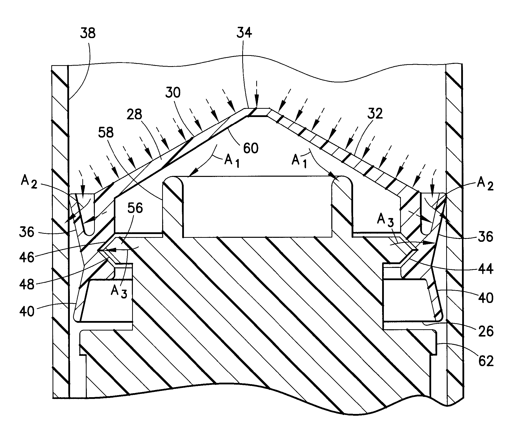
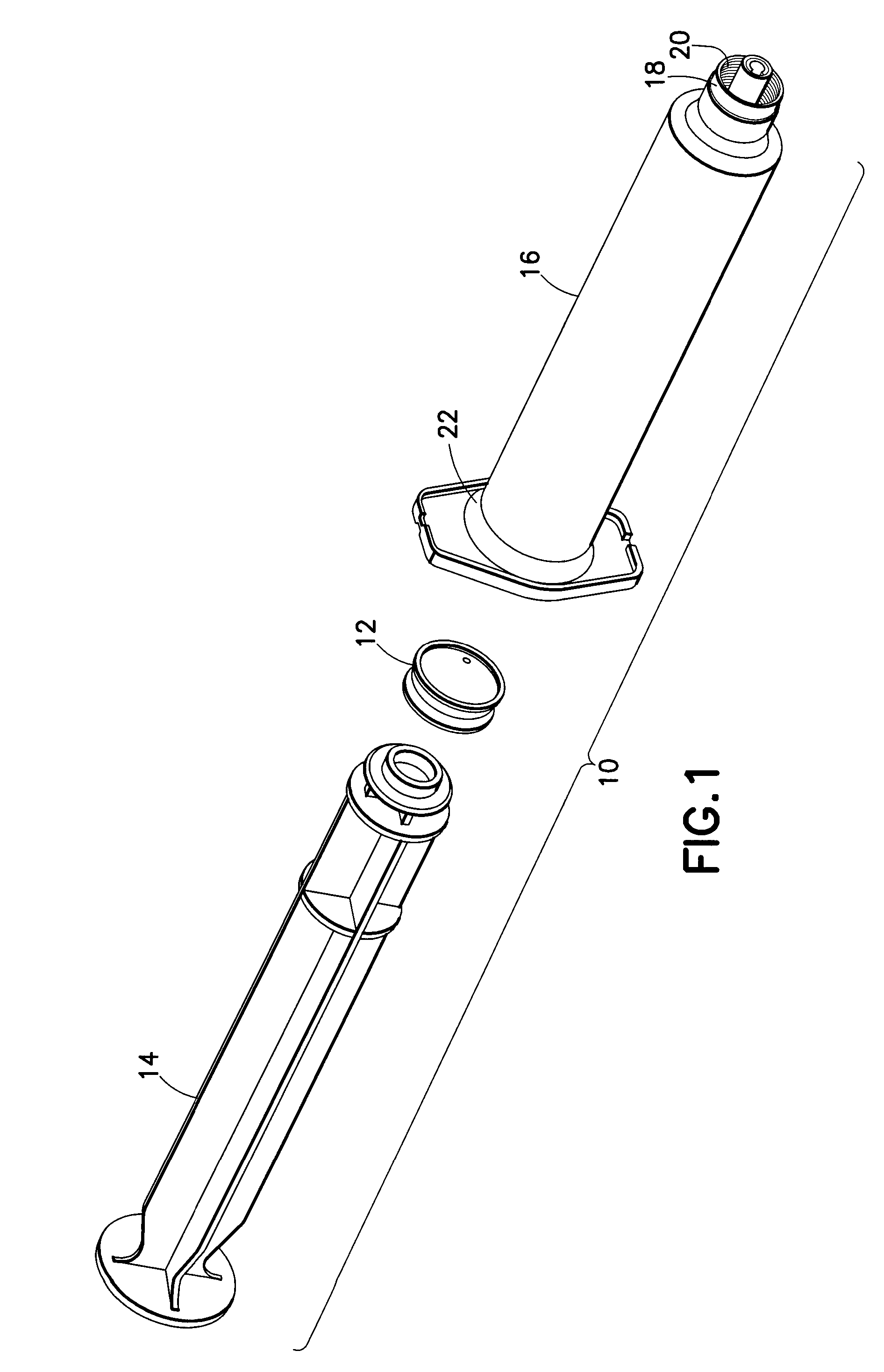
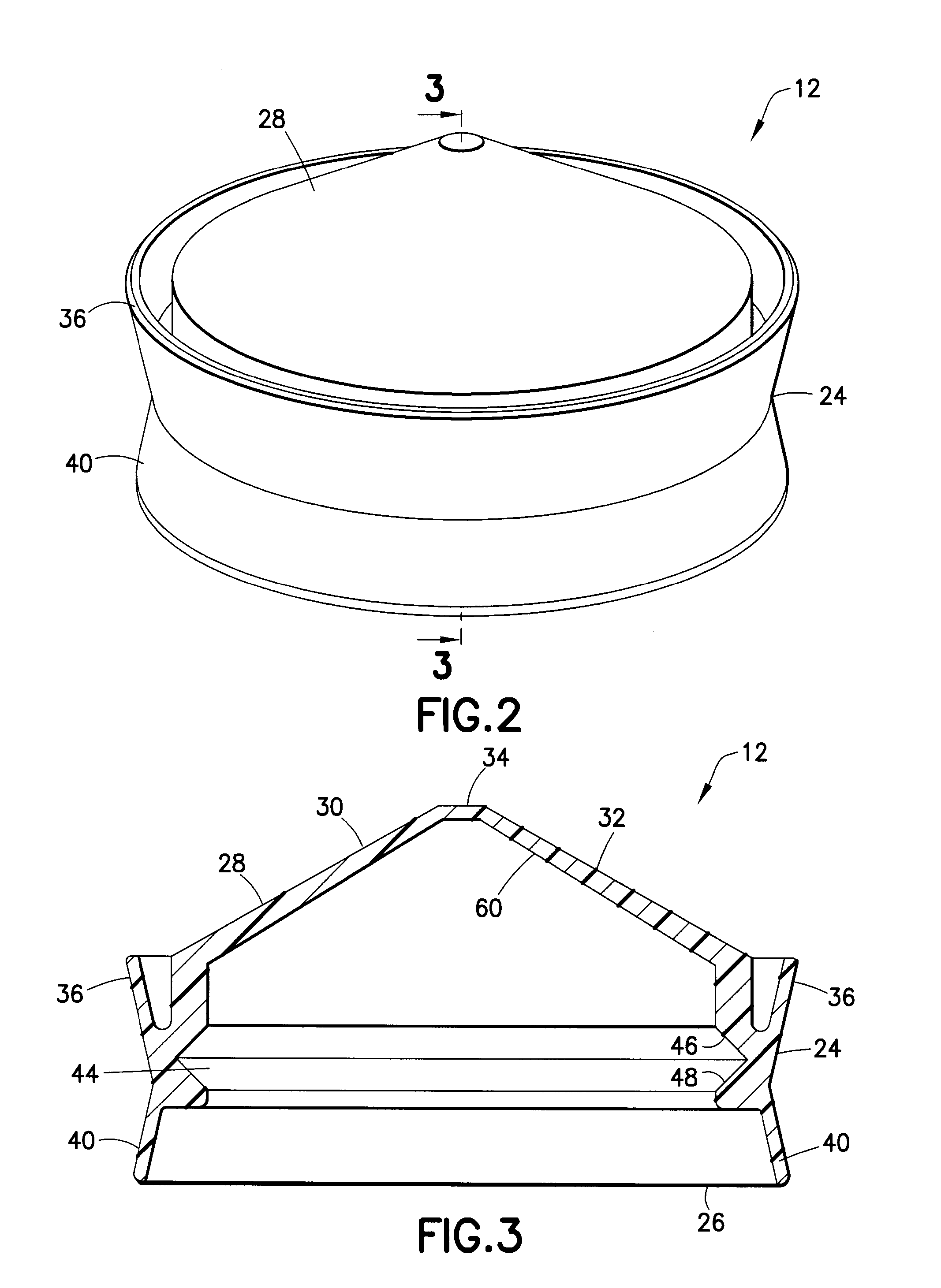
[0061]With reference to FIGS. 2 and 3, the stopper 12 includes a main body portion 24 defining an open rearward end 26 configured to receive the plunger rod 14 and a closed front end 28 that forms a flexible roof. The flexible roof has a thickness of about 0.1 mm to about 3 mm, and desirably a thickness of about 0.3 mm to about 1.2 mm. The closed front end 28 of the main body portion 24 includes a first angled portion 30 and a second angled portion 32, which are both part of a single conical surface, that extend toward a tip 34, thereby providing the closed front end 28 with a substantially conical appearance. However, this shape of the flexible roof is not to be considered as limiting the present invention as the roof may be flat. Such a roof would not provide flexing roof action in which a flexible roof of the stopper flexes inward and expands sideways in a radial direction. However, a stopper with a flat roof has been envisioned that includes a flexing skirt action in which a per...

second embodiment

[0075]With reference to FIGS. 8-10, a stopper in accordance with the present invention, generally denoted as reference numeral 112, is illustrated. The stopper 112 includes a main body portion 124 defining an open rearward end 126 configured to receive the plunger rod 14 and a closed front end 128 that forms a flexible roof. The closed front end 128 of the main body portion 124 includes a first angled portion 130 and a second angled portion 132, which are both part of the same conical surface that extends to a tip 134. The tip 134 includes an extended portion 135 configured to fit inside a tip of the syringe barrel 16 to minimize the space in the syringe barrel 16 where unused medication remains after an injection has been completed. The extended portion 135 may also be used during the assembly of the syringe 10 to aid in properly orienting the stopper 112 within the syringe barrel 16.

[0076]A first perimetrical skirt 136 is provided that extends around an outer circumference of the ...

third embodiment

[0080]With reference to FIGS. 11-13, the stopper, generally denoted as reference numeral 212, is illustrated. The stopper 212 includes a main body portion 224 defining an open rearward end 226 configured to receive an alternative embodiment of plunger rod 214 (see FIGS. 14 and 15) and a closed front end 228 that forms a flexible roof. The closed front end 228 of the main body portion 224 includes a first angled portion 230 and a second angled portion 232, which are both part of the same conical surface that extends to a tip 234. The tip 234 includes an extended portion 235 configured to fit inside a tip of the syringe barrel 16 to minimize the space in the syringe barrel 16 where unused medication remains after an injection has been completed. The extended portion 135 may also be used during the assembly of the syringe 10 to aid in properly orienting the stopper 112 within the syringe barrel 16.

[0081]A first perimetrical skirt 236 is provided that extends around an outer circumferen...


PUM


Abstract

A stopper includes a main body portion defining an open rearward end configured to receive the plunger rod, an engagement portion provided along an inner circumference of the main body portion configured to engage at least a top portion of the plunger rod, a closed front end forming a flexible roof, and a first perimetrical skirt extending around an outer circumference of the main body portion toward the closed front end of the main body portion. When fluid pressure is increased inside the syringe barrel during an injection, the flexible roof expands in a radial direction toward an inner wall of the syringe barrel, the first perimetrical skirt is forced against the inner wall of the syringe barrel, and an engagement between the plunger rod and the engagement portion forces the main body portion to expand in the radial direction toward the inner wall of the syringe barrel.

Description

CROSS REFERENCE TO RELATED APPLICATIONS[0001]This application claims the benefit of U.S. Provisional Patent Application No. 61 / 468,304 entitled “Plastic Stopper” filed Mar. 28, 2011, which is hereby incorporated by reference in its entirety.BACKGROUND OF THE INVENTION[0002]1. Field of the Invention[0003]The invention relates, in general, to a stopper assembly for use with a syringe and, more particularly, to a stopper assembly manufactured from a rigid or semi-rigid plastic material that provides an active sealing function.[0004]2. Description of Related Art[0005]Current syringe designs can typically be categorized as two-piece syringes or three-piece syringes. A typical three-piece syringe includes a tubular barrel having an access opening formed at one end, and a smaller discharge opening formed at the opposing end. The lead end of an elongated plunger is received within the access opening of the barrel so as to be slidable within the barrel. Attached to the lead end of the plunge...

Claims


Application Information

Patent Timeline
Patent Type & Authority Applications(United States)
IPC IPC(8): A61M5/315
CPCA61M2005/31516A61M5/31513A61M2005/31521A61M5/31515A61M5/3129
Inventor IVOSEVIC, MILANYEMANE TEKESTE, GIRUMWONG, ANDREWQUINN, MICHAEL VINCENTBARANSKI, ANDRZEJ
Owner BECTON DICKINSON & CO
Why Eureka
Try Eureka