
Scaffold for connective tissue repair

a connective tissue and scaffolding technology, applied in the field of scaffolding for connective tissue repair, can solve the problems of excessive stress placed on these soft tissues, partial or permanent disability, and associated risks of harvesting procedure, and achieve the effect of facilitating tissue ingrowth

Inactive Publication Date: 2012-10-04
DEPUY MITEK INC
View PDF21 Cites 49 Cited by
  • Summary
  • Abstract
  • Description
  • Claims
  • Application Information

AI Technical Summary

Benefits of technology

The scaffold provides initial mechanical strength similar to native tissue, supports tissue regeneration, and eliminates the drawbacks of autograft and synthetic implants by degrading over time, allowing for native tissue replacement without the risks associated with harvesting procedures.

Problems solved by technology

Such injuries generally result from excessive stresses being placed on these soft tissues.
If, however, the ligament or tendon is completely detached from its associated bone or bones, or if it is severed as the result of a traumatic injury, partial or permanent disability may result.
While autogeneic tissue grafts have been successfully used to replace connective tissue, the harvesting procedure, like any medical procedure, has associated risks.
Two primary concerns are tissue damage at the harvest site during the removal process and donor site morbidity.
Yet, even when the harvesting procedure is successfully performed, the sample may not provide a sufficient supply of tissue for a graft and / or the tissue may not have the desired quality or consistency.
However, the graft has potential ability to transmit disease and elicit an immune response.
There is also a lack of consistency in mechanical properties of the graft and the supply is limited.
However, the long term results, such as those that extend beyond one year, showed the mechanical failure of the these devices.
These prostheses have been found to lack sufficient strength and durability to act as a permanent replacement for the lifetime of the patient.
Other prostheses, such as some made from synthetic materials, have good physical properties, but can erode or cause bone erosion.

Method used


Image

  • Scaffold for connective tissue repair
  • Scaffold for connective tissue repair
  • Scaffold for connective tissue repair

Examples


example 1

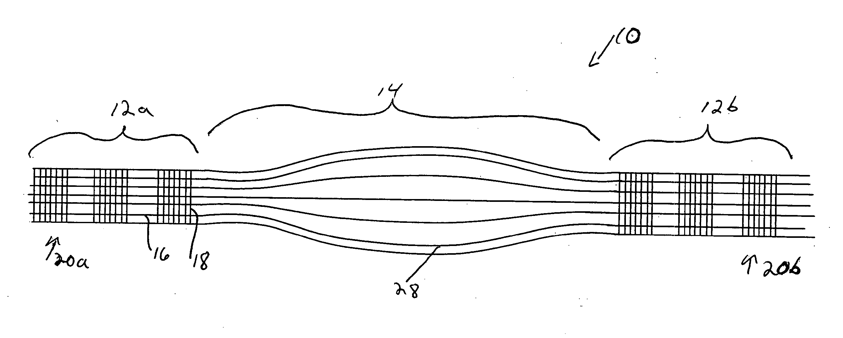
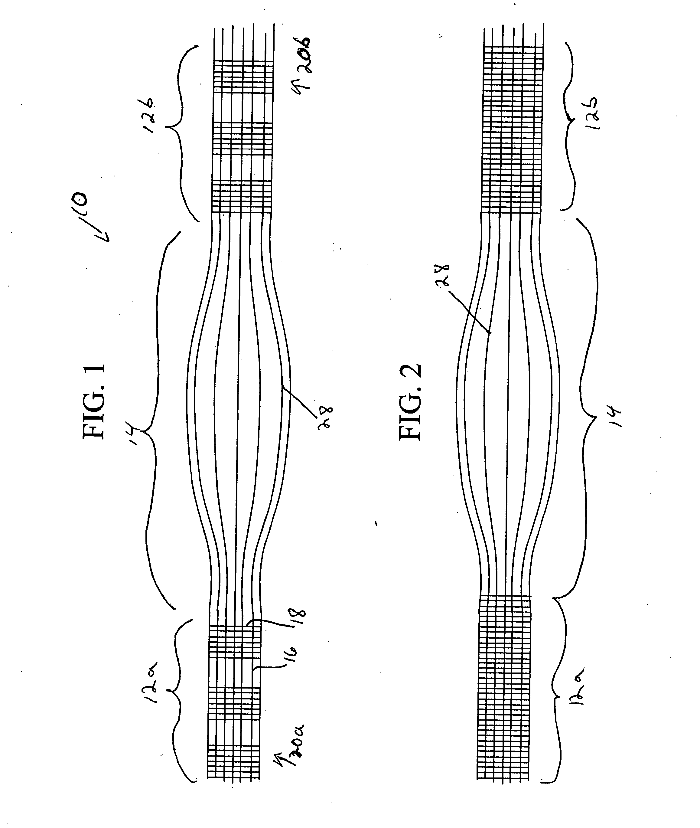
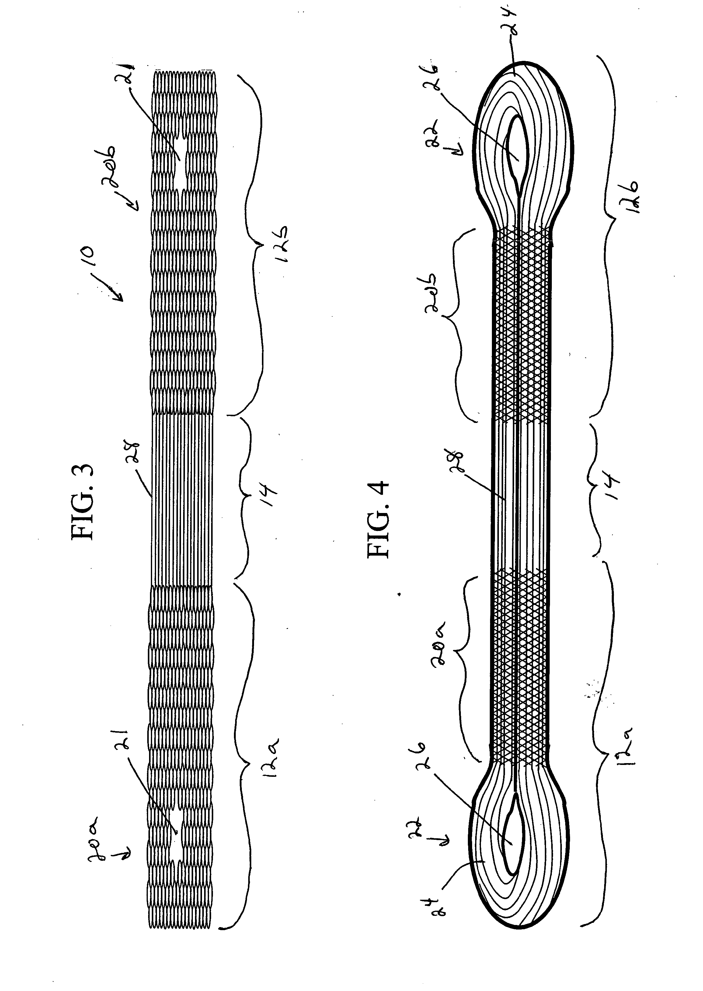
[0104]Native anterior cruciate ligament (ACL) tissue was excised from a goat knee and the ACL was reconstructed using a ligament graft resembling that of the type shown in FIG. 4. The graft was formed of PANACRL, a 95:5 copolymer of lactide and glycolide, and was prepared for implantation by incorporating into the graft about 2 ml. of platelet rich plasma (PRP). In one evaluation about 600 mg. minced ACL fragments (about 1 mm. in size) was also incorporated into the graft. The purpose of this study was to evaluate the potential of synthetic scaffolds with autologous growth factors and / or minced tissue to regenerate the ACL. The grafts were 3.5 mm in diameter and the PRP and the minced tissue were placed on the graft before insertion into the tibial and femoral bone tunnels. A VICRYL mesh was sutured around the PANACRYL graft and minced tissue to help retain the tissue on the graft. Fixation of the device was achieved on both the femoral and tibial side using a screw / washer system. A...

example 2

[0105]A synthetic ACL graft of the type shown in FIG. 4 and formed of PANACRYL, a 95:5 copolymer of lactide and glycolide, was tested mechanically in tension with a gauge length of 8 inches and a strain rate of 1 inch / min. The stiffness was measured to be 160 N / mm and the graft was found to have an ultimate tensile strength of 2600N.


PUM

PropertyMeasurementUnit
lengthaaaaaaaaaa
lengthaaaaaaaaaa
diameteraaaaaaaaaa

Abstract

A connective tissue scaffold including opposed first and second anchoring segments formed from a plurality of bioresorbable polymeric fibers oriented in a direction substantially parallel to a longitudinal axis of the scaffold and a plurality of bioresorbable polymeric fibers oriented in a direction substantially transverse to a longitudinal axis of the scaffold. A central segment joins the first and second anchoring segments and includes a plurality of bioresorbable polymeric fibers oriented in a direction substantially parallel to the longitudinal axis of the scaffold. The scaffold can also a tissue particle and / or biological component.

Description

CROSS REFERENCE TO RELATED APPLICATIONS[0001]This application is a divisional of U.S. patent application Ser. No. 10 / 610,362, filed Jun. 30, 2003, and entitled “SCAFFOLD FOR CONNECTIVE TISSUE REPAIR,” which is hereby incorporated by reference in its entirety.FIELD OF THE INVENTION[0002]This invention relates to prosthetic devices for repairing and replacing torn or damaged connective tissue such as ligaments and tendons.BACKGROUND OF THE INVENTION[0003]The complete or partial detachment of ligaments, tendons or other soft tissues from their associated bones within the body is a relatively common injury, particularly among athletes. Such injuries generally result from excessive stresses being placed on these soft tissues. For example, a tissue-detaching injury may occur as the result of an accident such as a fall, overexertion during a work-related activity, during the course of an athletic event, or in any one of many other situations and / or activities.[0004]In the case of a partial...

Claims


Application Information

Patent Timeline
Patent Type & Authority Applications(United States)
IPC IPC(8): A61F2/08A61L27/00A61L27/18A61L27/36A61L27/56
CPCA61F2/08A61L27/18A61L27/3604A61L27/3641A61L27/56A61L27/3645C08L67/04A61F2210/0004A61F2250/0015A61F2250/0028A61F2002/0852A61L27/3662A61L27/3691A61L27/58
Inventor HWANG, JULIAHAMMER, JOSEPHSCHWARTZ, HERBMALAVIYA, PRASANNA
Owner DEPUY MITEK INC
Learn More