
Heat exchanger plate and an evaporator with such a plate

a technology of heat exchanger plate and evaporator, which is applied in the direction of stationary plate conduit assembly, lighting and heating apparatus, laminated elements, etc., can solve the problems of extreme volume flow of exhaust gas and temperature fluctuations

Inactive Publication Date: 2012-10-11
STEAMDRIVE
View PDF3 Cites 8 Cited by
  • Summary
  • Abstract
  • Description
  • Claims
  • Application Information

AI Technical Summary

Benefits of technology

[0024]A transverse flow distribution device is provided in accordance with the invention in the direction of the longitudinal axis between the inlet and the at least one flow channel extending in the direction of the longitudinal axis and / or between the at least one flow channel extending in the direction of the longitudinal axis and the outlet, which transverse distribution device compensates pressure losses in the flow of the medium to be evaporated which are caused by the length of the flow path between the inlet and the various positions of the inlet in the at least one flow channel or—in the case of several flow channels extending adjacent to one another in the direction of the longitudinal axis—between the inlet and the entrances of the various flow channels. As already explained above, the transverse flow distribution device can either be provided in the region between the inlet and the at least one flow channel extending in the direction of the longitudinal axis in which the pressure losses caused by the length of the flow path are provided when the medium to be evaporated passes through this region in different ways. It is achieved by the compensation of the various pressure losses caused by the length of the flow path that the medium to be evaporated will be distributed evenly among all flow channels extending in the direction of the longitudinal axis or the entire cross-section of a flow channel extending in the direction of the longitudinal axis, irrespective of the respective actual position of the inflow into the flow channel relative to the position of the inlet or—if a separate inflow channel is provided between the inlet and the transverse flow distribution device—irrespective of the position of the outlet from the inflow channel relative to the entrance into the at least one flow channel extending in the direction of the longitudinal axis. Alternatively, this even distribution of flow in the at least one flow channel extending in the direction of the longitudinal axis or all flow channels extending in the direction of the longitudinal axis can also be achieved by a respective pressure buildup from behind by a transverse flow distribution device, which is arranged in the direction of flow or in the direction of the longitudinal axis behind the at least one flow channel extending in the direction of the longitudinal axis and therefore between said flow channel and the outlet. It is further possible to provide a transverse flow distribution device before and after the at least one flow channel extending in the direction of the longitudinal axis, which may also cooperate concerning the pressure buildup from behind.
[0029]When the medium to be evaporated flows out of the inflow channel, it should be distributed as evenly as possible for optimal evaporation over the entire flow cross-section of the flow channel arranged in the direction of the longitudinal axis of the heat exchanger plate or over all adjacently arranged flow channels extending in the longitudinal direction of the heat exchanger plate. This can be achieved according to the invention in such a way that a transverse flow distribution device is provided between the meandering inflow channel and the at least one flow channel extending in the direction of the longitudinal axis, which transverse flow distribution device compensates pressure losses caused by the length of the flow path between the outlet from the inflow channel and the various positions of the inlet into the at least one flow channel or the various inlets of the various flow channels. The transverse flow distribution device increases the flow resistance on the comparatively short distances between the outlet of the medium to be evaporated from the inflow channel and the entrance into the at least one flow channel arranged in the longitudinal direction in comparison with the comparatively longer distances between said outlet and entrance points positioned further away. Such a transverse flow distribution device can also be provided which sets the flow resistance on the individual paths to be covered by the medium to be evaporated from the outlet and the individual entrance points in such a way that uneven heat supply via the heat exchange of plates is compensated.
[0032]An alternative or additional measure for compensating pressure losses caused by the length of the flow path provides a throttling point in the direction of the longitudinal axis between the meandering inflow channel and the at least one flow channel extending in the direction of the longitudinal axis, which throttling point is provided over the entire width of the at least one flow channel extending in the direction of the longitudinal axis and causes the backing up of the medium to be evaporated over the entire width of the at least one flow channel extending in the direction of the longitudinal axis. Said backing up is so strong that the pressure loss via the throttling point—before the medium to be evaporated enters into the at least one flow channel extending in the direction of the longitudinal axis—far exceeds the various pressure losses caused by the length of the flow path before the throttling point.

Problems solved by technology

Finally, the problem arises during use in the exhaust gas flow of an internal combustion engine that the volume flow of the exhaust gas will vary extremely during operation of the internal combustion engine and is further subject to temperature fluctuations.

Method used


Image

  • Heat exchanger plate and an evaporator with such a plate
  • Heat exchanger plate and an evaporator with such a plate
  • Heat exchanger plate and an evaporator with such a plate

Examples


Embodiment Construction

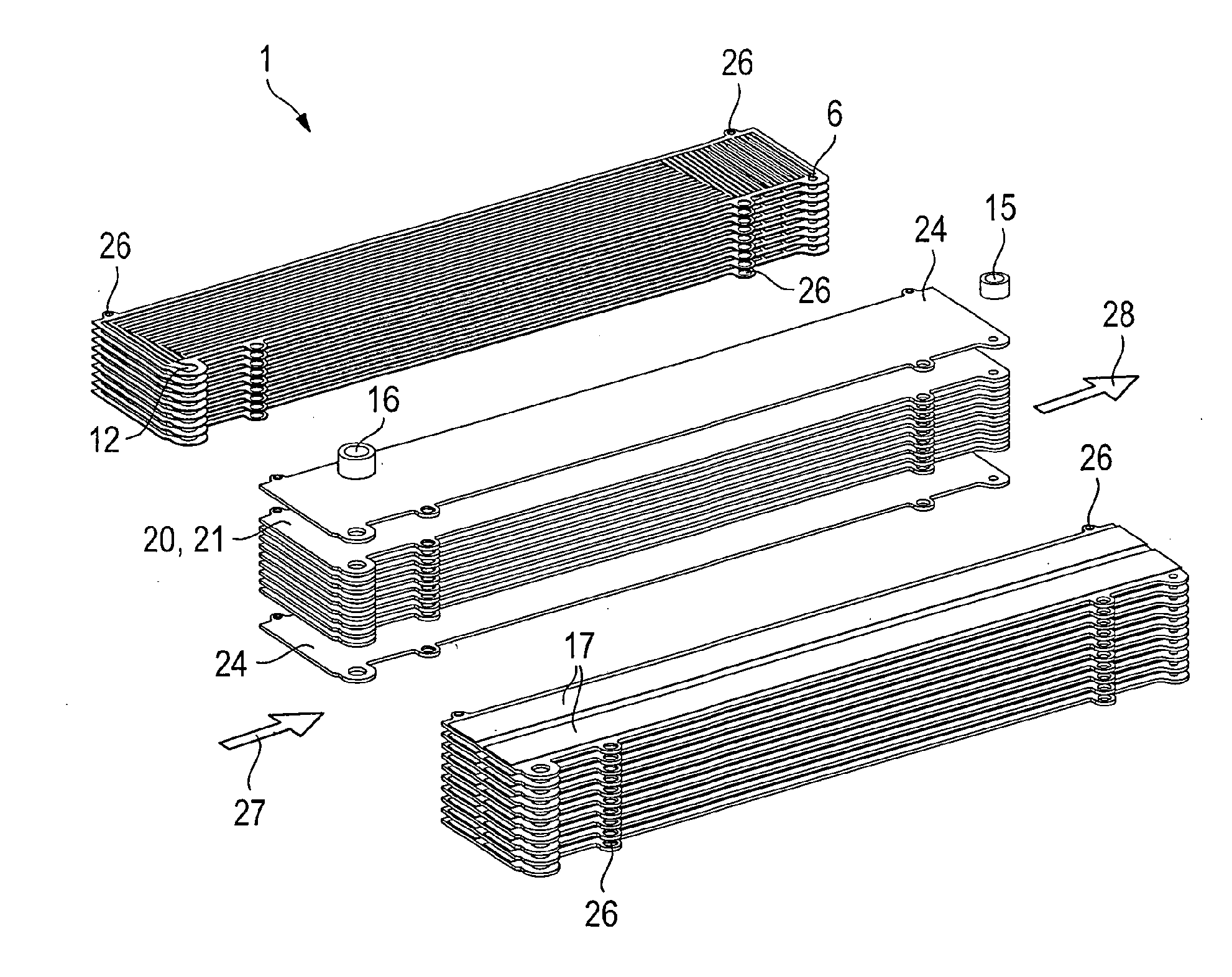
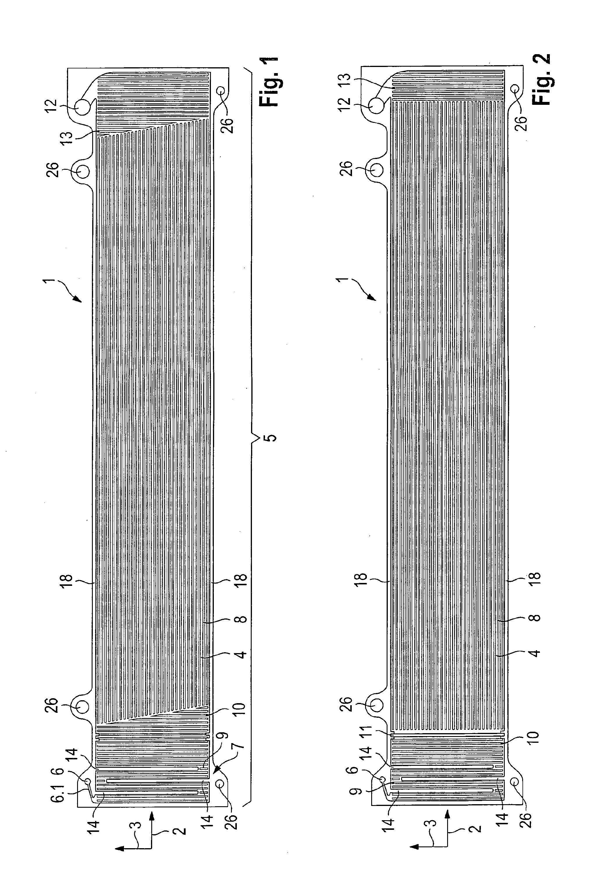
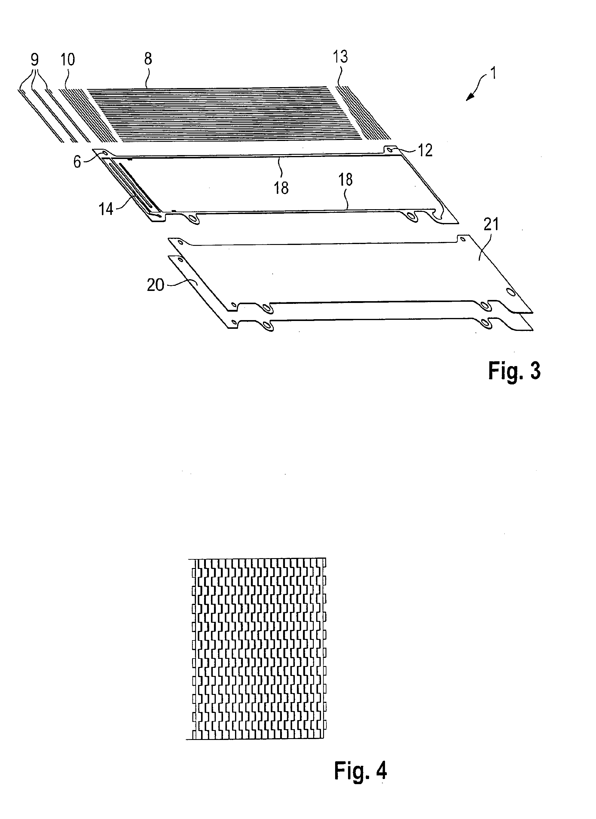
[0053]FIG. 1 shows a top view of a heat exchanger plate 1 in accordance with the invention for an evaporator, with a plurality of such heat exchanger plates 1 usually being provided to be stacked one above the other in a respective evaporator. A longitudinal axis 2 and a transverse axis 3 are shown in the drawing for easier spatial allocation.

[0054]A plurality of flow channels 4 extend over the axially largest area of the heat exchanger plate 1 in the direction of the longitudinal axis 2, which conduct the medium to be evaporated. In the illustrated embodiment, the individual flow channels 4 are separated from one another by the plates 8. As is also shown, the flow channels 4 further extend over the entire width of the heat exchanger plate 1, as seen in the direction of view towards the longitudinal axis 2 and in the direction of flow of the medium to be evaporated in the flow channels 4. Webs 18 are further only provided on the two lateral edges, which—as will be shown especially i...


PUM


Abstract

A heat exchanger plate for an evaporator includes a flow transverse distribution device. Disks of the flow transverse distribution device conduct the medium to be evaporated to the flow channel extending in the direction of the longitudinal axis. The disks include openings allowing a flow of the medium in the direction of the longitudinal axis with comparatively higher flow resistance than in the direction of the transverse axis. The number of disks arranged one behind the other in the direction of the longitudinal axis varies over the width of the heat exchanger plate in the direction of the transverse axis. On each width section, in which the entry of the medium into the disks arranged one behind the other is intended, the comparatively largest number of disks is provided one behind the other. As the distance from the entrance increases, the number decreases in the direction of the transverse axis.

Description

CROSS REFERENCE TO RELATED APPLICATIONS[0001]This is a continuation of PCT application No. PCT / EP2010 / 006467, entitled “HEAT EXCHANGER PLATE AND EVAPORATOR COMPRISING THE SAME”, filed Oct. 22, 2010, which is incorporated herein by reference.BACKGROUND OF THE INVENTION[0002]1. Field of the Invention[0003]The present invention relates to a heat exchanger plate for an evaporator and an evaporator with a plurality of heat exchanger plates which are stacked above one another, especially for a drive train of a motor vehicle, rail vehicle or a ship for example, comprising an internal combustion engine and a steam motor, with the heat of a hot medium such as a hot exhaust air flow, hot charge air, coolant, cooling agent or an oil of the internal combustion engine or a further unit provided in the drive train such as a vehicle air-conditioning system being used in the evaporator for generating the steam for the steam motor. The present invention is not limited to the application in a mobile ...

Claims


Application Information

Patent Timeline
Patent Type & Authority Applications(United States)
IPC IPC(8): F28D15/00F01N5/02
CPCF28D9/0068F28F3/027F28D9/0075
Inventor BERGER, JURGENAMBROS, PETERFEZER, AXELORSO, JOCHENNECKER, HARALD
Owner STEAMDRIVE
Learn More