
Wiper controller

a controller and wiper technology, applied in the field of wiper controllers, can solve the problem that the unwiped region is not unnecessarily smaller, and achieve the effect of not unnecessarily reducing the size of the unwiped area

Active Publication Date: 2012-10-11
ROBERT BOSCH GMBH
View PDF2 Cites 4 Cited by
  • Summary
  • Abstract
  • Description
  • Claims
  • Application Information

AI Technical Summary

Benefits of technology

[0005]In this way, load peaks acting on the windshield wiping device can be reduced as a function of the position of the wiper shaft. Therefore, in particular a nonuniform transmission characteristic of the gear with respect to a position of the wiper shaft can be taken into account during the reduction of the load peaks. By reversing the direction of rotation, areas in which obstacles are present are excluded from the wiping process, said areas increasing the loading on the windshield wiping device to a particularly high degree owing to the nonuniform transmission characteristic. The controller can also advantageously be used for windshield wiping devices having a gear with a uniform transmission characteristic. By reversing the direction of rotation, it is possible to reduce a time period of a high blocking torque, which can increase the expected service life of the windshield wiping device.
[0006]In addition, it is possible to determine whether the torque of the output device exceeds the predetermined torque more often than a predetermined frequency. Random or temporary load peaks do not in this way necessarily give rise to premature reversal of the direction of rotation of the drive device, with the result that an unwiped region is not unnecessarily made smaller. Preferably, a low predetermined frequency is assigned to a high predetermined torque. The entire windshield wiping device can therefore be protected against load peaks, which can lengthen a service life of the windshield wiping device.
[0007]Furthermore, it is possible to determine whether the torque of the drive device exceeds the predetermined torque for longer than a predetermined time. In a similar way to that stated above, this can promote reduction of those load peaks which can shorten a service life of the windshield wiping device to a particular degree. A short predetermined time is preferably assigned to a high predetermined torque.
[0009]This combination permits system loading of the windshield wiping device to be made significantly more uniform as a result of which an overall service life expectation of the windshield wiping device increases and elements of the windshield wiping device can be dimensioned better. In addition, elements can, if appropriate, be given weaker dimensioning without putting at risk a planned service life of the windshield wiping device.

Problems solved by technology

Random or temporary load peaks do not in this way necessarily give rise to premature reversal of the direction of rotation of the drive device, with the result that an unwiped region is not unnecessarily made smaller.

Method used


Image

  • Wiper controller
  • Wiper controller
  • Wiper controller

Examples


Embodiment Construction

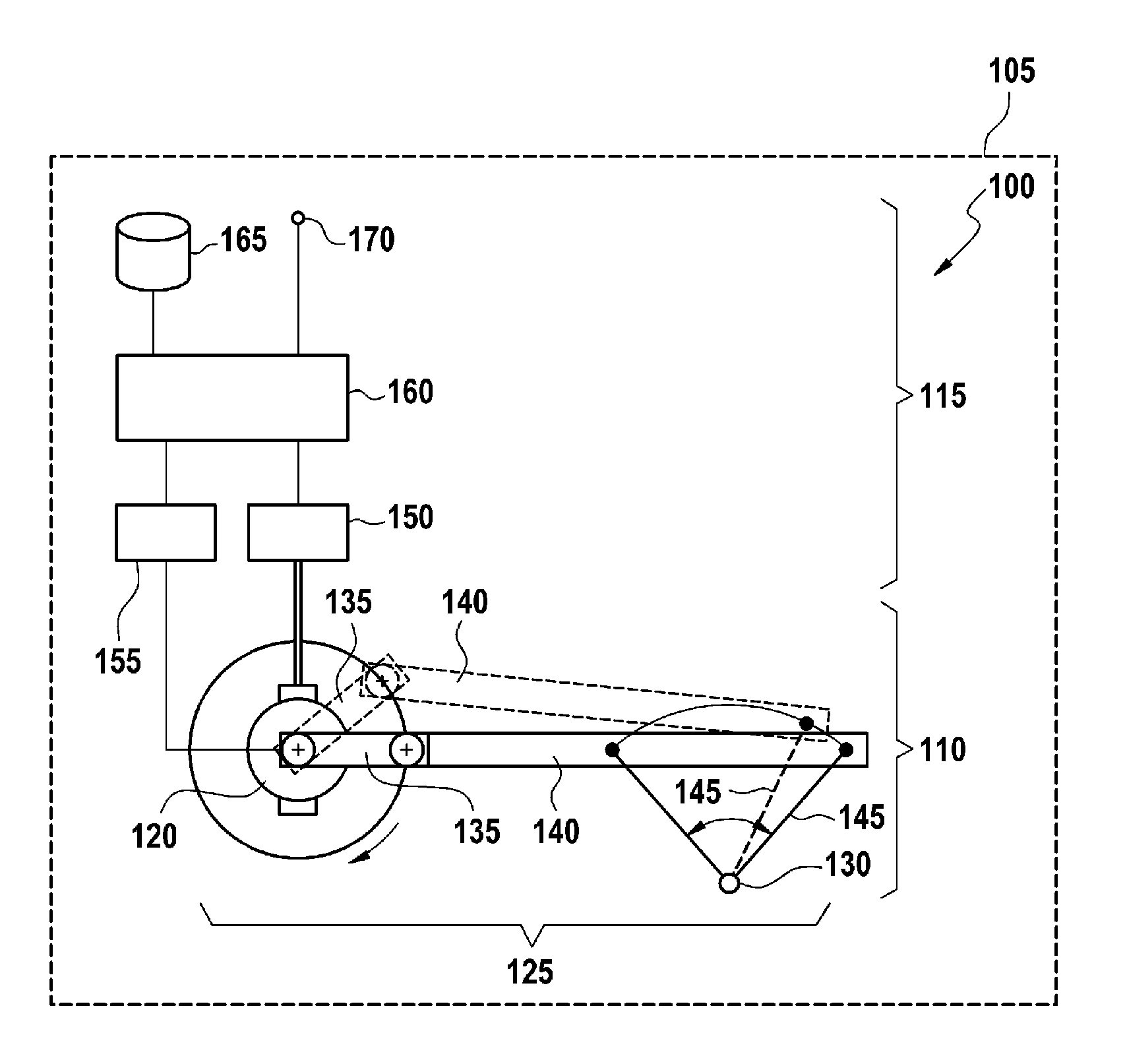
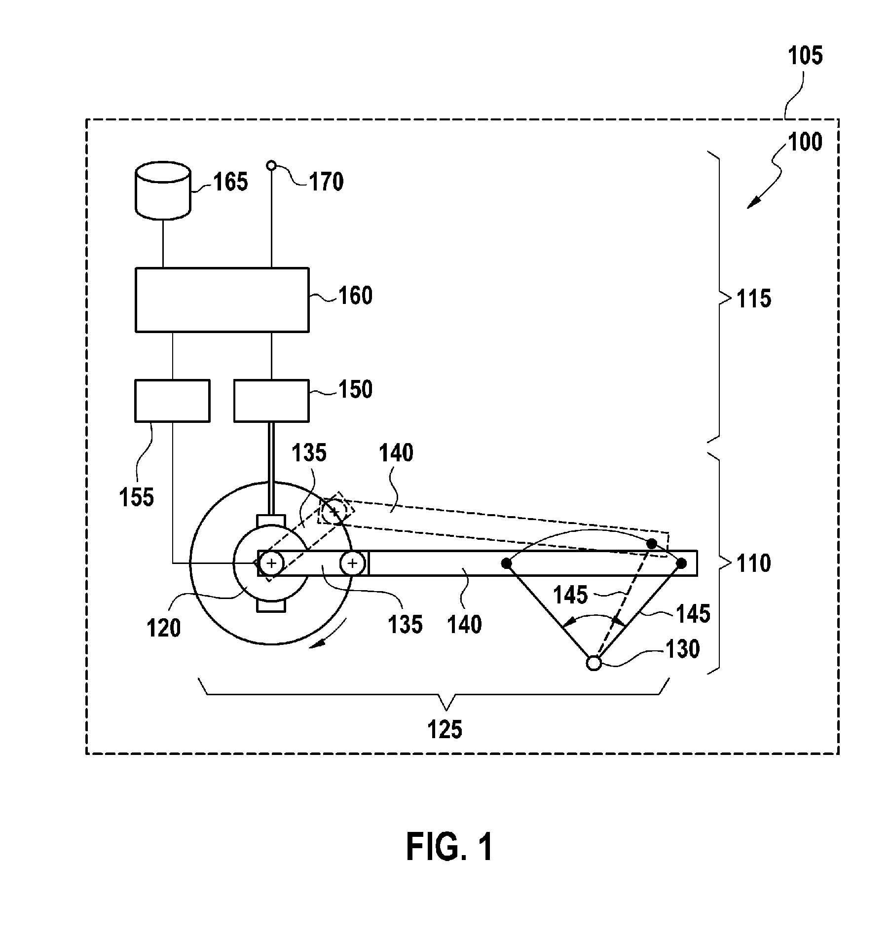
[0015]FIG. 1 shows a windshield wiping system 100 on board a motor vehicle 105. The windshield wiping system 100 comprises a windshield wiping device 110 and a controller 115. The windshield wiping device 110 comprises a drive device 120, a gear 125 and a wiper shaft 130. The gear 125 is formed by a drive crank 135, a linkage 140 and an output lever 145. The gear 125 can have further gear elements, in particular a worm gear (not illustrated) which steps down a rotational movement of the drive device 120 to the drive crank 135.

[0016]During operation of the windshield wiping device 110, the drive device 120 turns the drive crank 135, with the result that the pushrod 140 moves the output lever 145 about the wiper shaft 130 in an oscillating fashion in a circular segment. The direction in which the drive crank 135 is turned by the drive device 120 is irrelevant for this activation.

[0017]A wiper arm, which is connected to the wiper shaft 130 and guides a wiper blade over a window of the ...


PUM


Abstract

A windshield wiper device comprises a controller, a drive unit and a gear that transmits the movement of the drive unit to a wiper shaft. The controller comprises a comparison unit for determining whether the torque output by the drive unit exceeds the predetermined torque, wherein the predetermined torque depends on the position of the wiper shaft. The wind shield wiper device further comprises a reversing unit for reversing the direction of rotation of the drive unit depending on the result of the comparison unit.

Description

BACKGROUND OF THE INVENTION[0001]Wiper systems such as are used, for example, in motor vehicles have the function of moving wiping blades over a window in order to clear the window of moisture and dirt. The wiping blades usually follow an oscillating movement in a circular segment. If the window is wet and if there are no foreign bodies on the window, only a relatively small drive torque has to be made available by the wiper system. However, occasionally there are obstacles located on the window, such as, for example, compressed snow at one end of the circular segment. In this case, the wiper system has to make available a large drive torque and the loading on the wiper system, which promotes wear, is high.[0002]DE 101 44 985 A1 proposes limiting a drive torque, which is made available by the wiper system, as a function of a position of the wiping blades. As a result, load peaks can be limited and overloading of the wiper system can be avoided.[0003]The invention is based on the obj...

Claims


Application Information

Patent Timeline
Patent Type & Authority Applications(United States)
IPC IPC(8): G06F7/00
CPCB60S1/08
Inventor ZIMMER, JOACHIM
Owner ROBERT BOSCH GMBH
Learn More