

Method for the prediction of fatigue life for welded structures
a technology of welded structure and fatigue life, which is applied in the direction of complex mathematical operations, instruments, design optimisation/simulation, etc., can solve the problems of large number of fe's, prohibitively complex 3d fe models, and inability to accurately determine stress concentration at the weld to
- Summary
- Abstract
- Description
- Claims
- Application Information
AI Technical Summary
Problems solved by technology
Method used
Image

Examples
Embodiment Construction
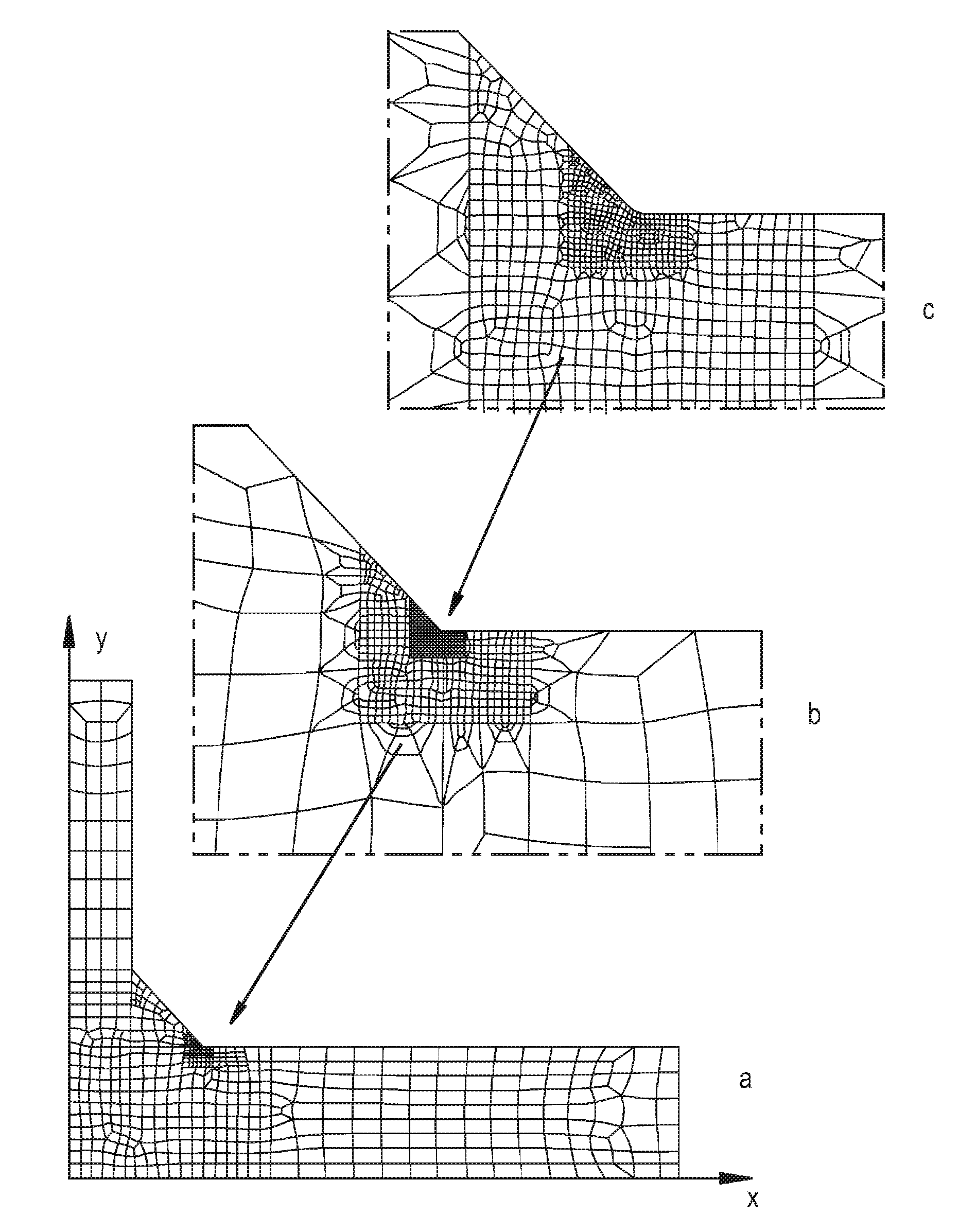
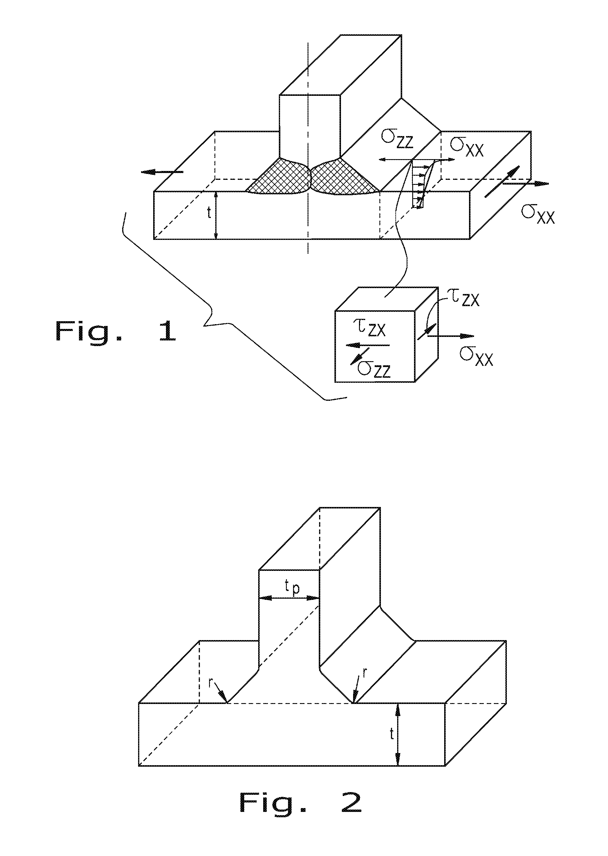
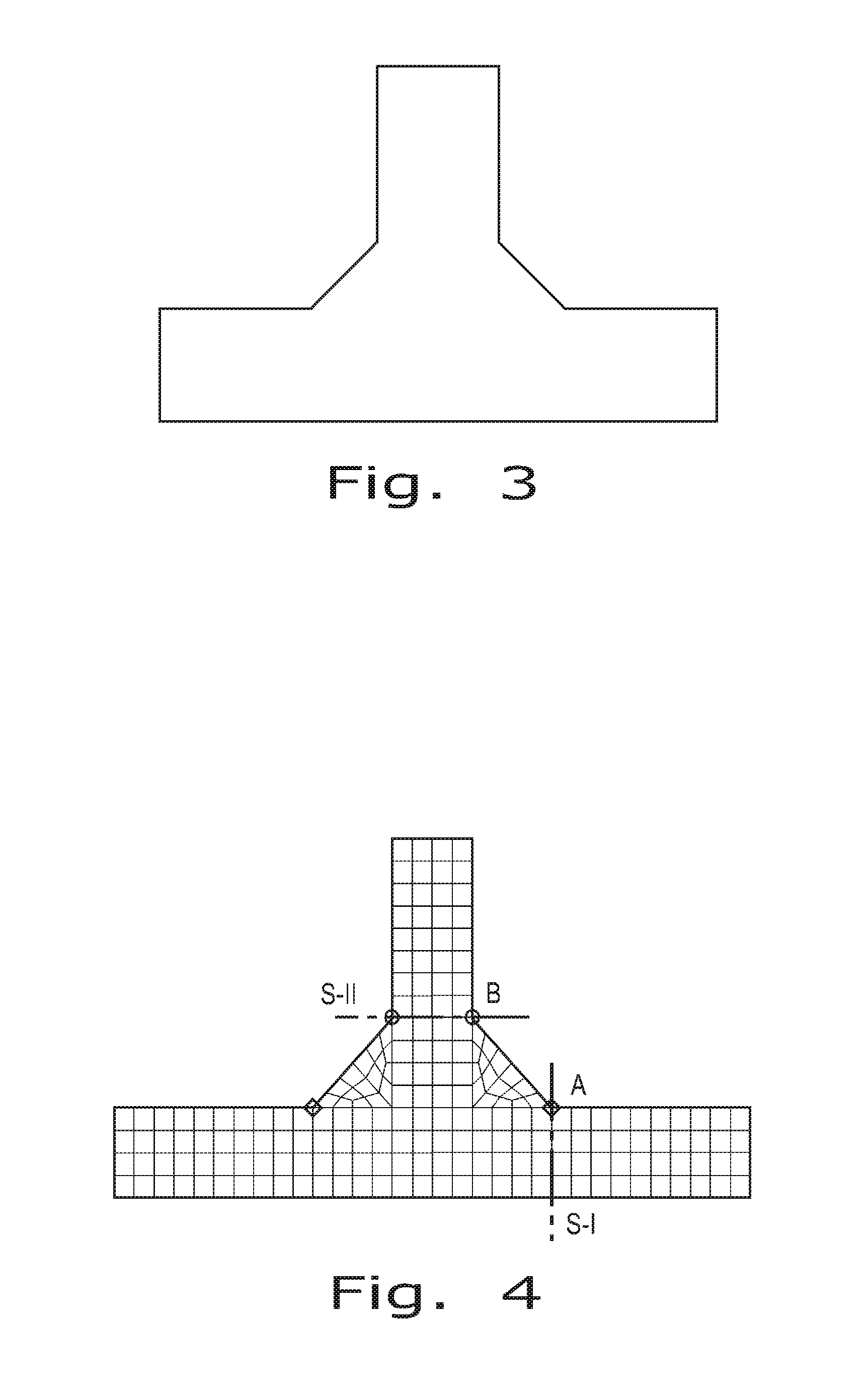
[0039]Referring now to the drawings, the method of the present invention for determining the fatigue life of a welded structure will be described in greater detail. The methodology of the present invention is sequentially set forth below, along with generalized mathematical equations and equations for a specific example of a welded structure. In the specific example, the welded structure is assumed to be a 3D geometry of a double fillet T-joint as shown in FIG. 1 including all geometrical details. Any such structure like that one (FIG. 2) can be often modeled using either 3D coarse or 3D fine FE mesh. When the coarse FE mesh is used the weld toe is modeled as a sharp corner as shown in FIG. 3. Because the purpose of the coarse FE mesh analysis is not to get stresses in the weld toe region then relatively large finite elements can be used. (The smallest finite element size, in the method described below, does not need to be less than 25% of the plate thickness ‘t’ or the weld length ...
PUM
 Abstract
Description
Claims
Application Information