Multi-Element Airfoil System

Inactive Publication Date: 2012-10-18
NASA
View PDF4 Cites 18 Cited by
  • Summary
  • Abstract
  • Description
  • Claims
  • Application Information

AI Technical Summary

Benefits of technology

[0011]It is another object of the present invention to provide a multi-element airfoil system that closes the gap between the trailing edge of the slat (or the leading edge of the flap) and the main airfoil element to provide a continuous surface for the flow on the low-pressure surface of the airfoil. The gap fil

Problems solved by technology

The sensor is in communication with the uncoupling device, and the sensor can cause t

Method used


Image

  • Multi-Element Airfoil System
  • Multi-Element Airfoil System
  • Multi-Element Airfoil System

Examples


Example

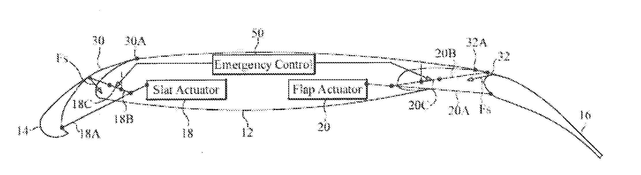
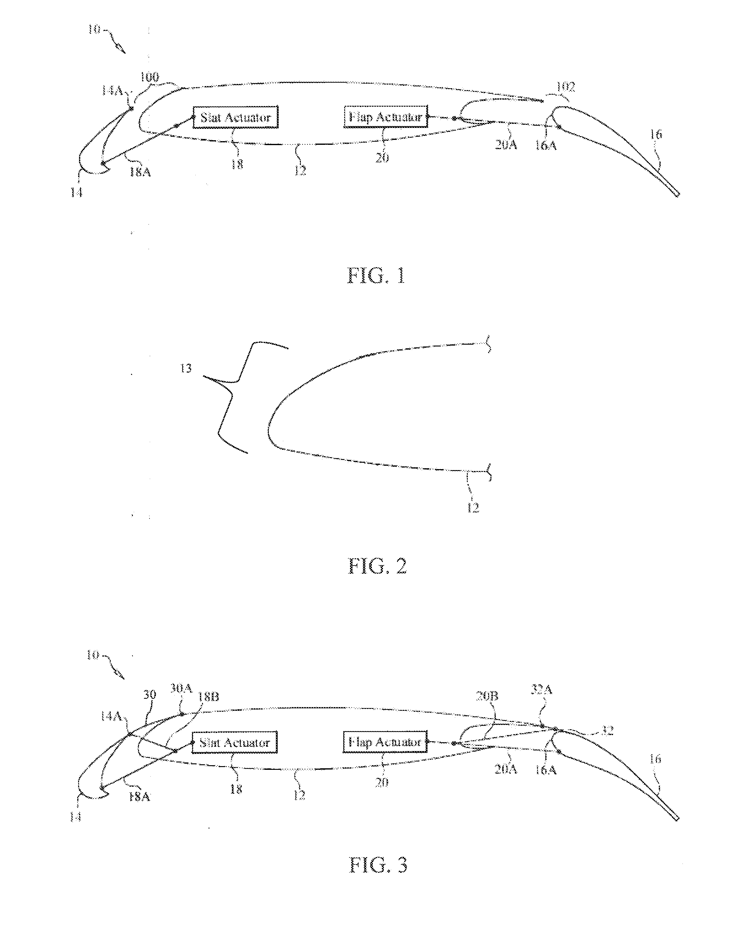
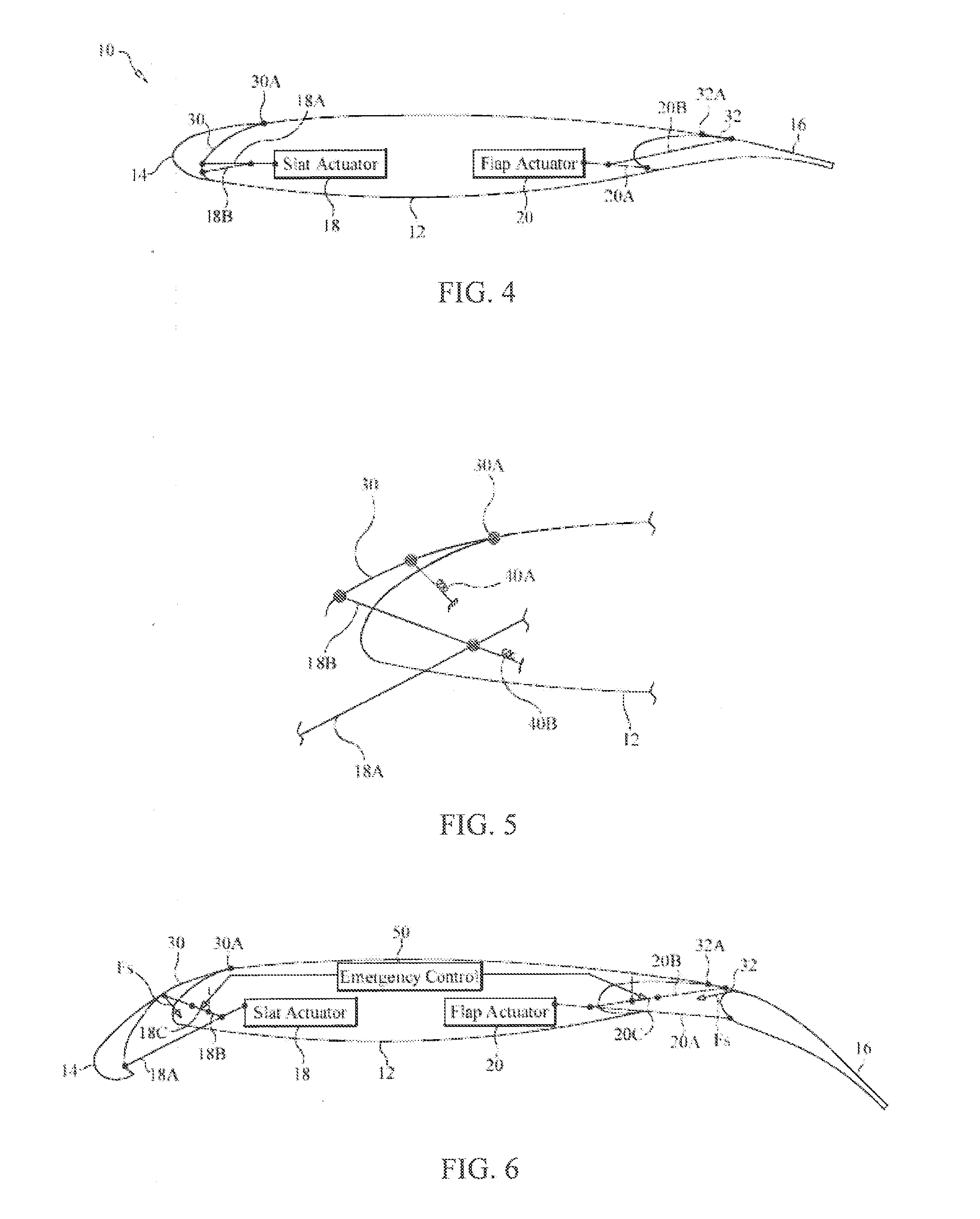
[0018]Referring now to the drawings, a multi-element airfoil system is illustrated schematically and is referenced generally by numeral 10. For clarity of illustration, the particular shapes of the various elements and / or their relative sizes are not limitations of the present invention as the shapes and sizes of the elements presented in the drawings merely facilitate a description of the present invention.

[0019]As shown in FIGS. 1 and 2, airfoil system 10 includes a main airfoil element 12, a deployable slat 14 spanning a portion of a leading edge region 13 of main airfoil element 12, and a deployable flap 16 spanning a portion of the trailing edge region of main airfoil element 12. While some multi-element airfoil systems only make use of a deployable flap or a deployable slat, many transportation aircraft have airfoil systems using both slats and flaps. Accordingly, the present invention will be described for both deployable slats and flaps, but it is to be understood that the p...


PUM


Abstract

A multi-element airfoil system includes an airfoil element having a leading edge region and a skin element coupled to the airfoil element. A slat deployment system is coupled to the slat and the skin element, and is capable of deploying and retracting the slat and the skin element. The skin element substantially fills the lateral gap formed between the slat and the airfoil element when the slat is deployed. The system further includes an uncoupling device and a sensor to remove the skin element from the gap based on a critical angle-of-attack of the airfoil element. The system can alternatively comprise a trailing edge flap, where a skin element substantially fills the lateral gap between the flap and the trailing edge region of the airfoil element. In each case, the skin element fills a gap between the airfoil element and the deployed flap or slat to reduce airframe noise.

Description

CROSS-REFERENCE TO RELATED PATENT APPLICATIONS[0001]This patent application claims the benefit of and priority to U.S. Provisional Patent Application No. 61 / 476,528, filed on Apr. 18, 2011, which is incorporated by reference in its entirety.STATEMENT REGARDING FEDERALLY SPONSORED RESEARCH OR DEVELOPMENT[0002]The invention was made in part by employees of the United States Government and may be manufactured and used by or for the Government of the United States of America for governmental purposes without the payment of any royalties thereon or therefor.FIELD OF THE INVENTION[0003]This invention relates to multi-element airfoils. More specifically, the invention is a multi-element airfoil system that fills one or more gaps formed between the multiple airfoil elements in order to reduce airframe noise or otherwise affect the aerodynamic characteristics.BACKGROUND OF THE INVENTION[0004]Noise produced by the established unsteady flow around aircraft structures, termed airframe noise, i...

Claims


Application Information

Patent Timeline
IPC IPC(8): B64C3/50B64C13/16
CPCB64C7/00B64C9/02Y02T50/32B64C9/24B64C2009/143B64C9/18B64C9/14Y02T50/30
Inventor TURNER, TRAVIS L.KHORRAMI, MEHDI R.LOCKARD, DAVID P.MCKENNEY, MARTIN J.ATHERLEY, RAYMOND D.KIDD, REGGIE T.
Owner NASA
Why Eureka
Try Eureka