Skew suppression method and optical transmission system

a technology of optical transmission system and suppression method, which is applied in the direction of optical transmission, electromagnetic transmission, transmission monitoring, etc., can solve the problems of deterioration of optical transmission system characteristics, adversely affecting the quality of signals recovered by digital signal processors, etc., and achieve the effect of suppressing a skew

Inactive Publication Date: 2012-10-18
FUJITSU LTD
View PDF31 Cites 55 Cited by
  • Summary
  • Abstract
  • Description
  • Claims
  • Application Information

AI Technical Summary

Benefits of technology

[0009]According to an aspect of the invention, a method for suppressing a skew between a first channel and a second channel in an optical transmission system having a transmitter that transmits an optical signal with the first channel and the second channel and a receiver that receives the optical signal, the method includes: controlling dispersion added to the optical signal to be larger than a specified amount; controlling a delay time of at least one of the ...

Problems solved by technology

The skew may adversely affect the quality of signals recovered by the digital signal proc...

Method used


Image

  • Skew suppression method and optical transmission system
  • Skew suppression method and optical transmission system
  • Skew suppression method and optical transmission system

Examples


first embodiment

[0061]FIG. 4 illustrates a relationship among skew, chromatic dispersion, and Q factor. In FIG. 4, the horizontal axis indicates a skew compensation amount provided in the receiver 4. The vertical axis indicates the Q factor. The Q factor indicates the quality of received signals. For example, Q factor is calculated based on the number of corrected errors counted by a FEC (forward error correction) circuit.

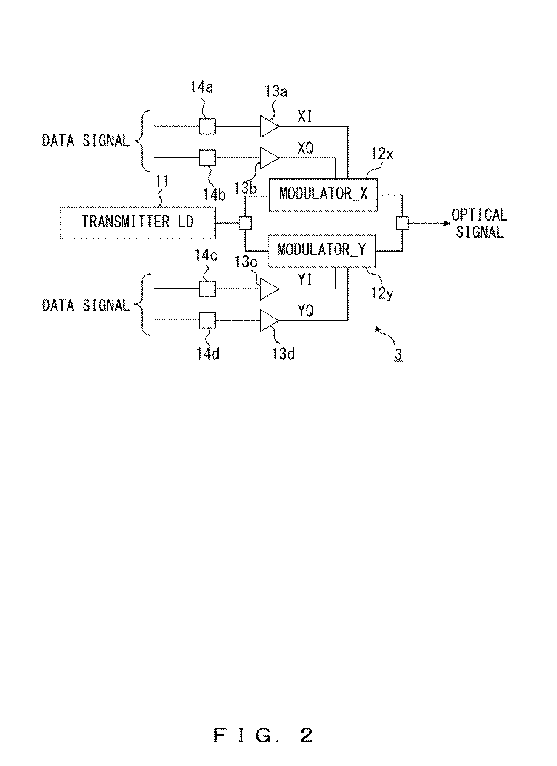
[0062]The graph illustrated in FIG. 4 is obtained by simulations under the following conditions. The difference between the frequency of the transmitter LD 11 and the frequency of the local LD 22 (i.e., frequency offset) is zero. The skew between I / Q generated in the transmitter 3 is +9 ps. The skew between I / Q generated in the receiver 4 is −9 ps. The line width of the transmitter LD 11 and the local LD 22 is 100 kHz. The optical signal-to-noise ratio (OSNR) is 15 dB. The skew between I / Q generated in the transmitter 3 is hereinafter referred to as “Tx skew”, and the skew between...

second embodiment

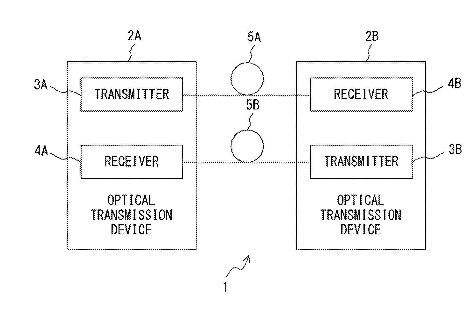
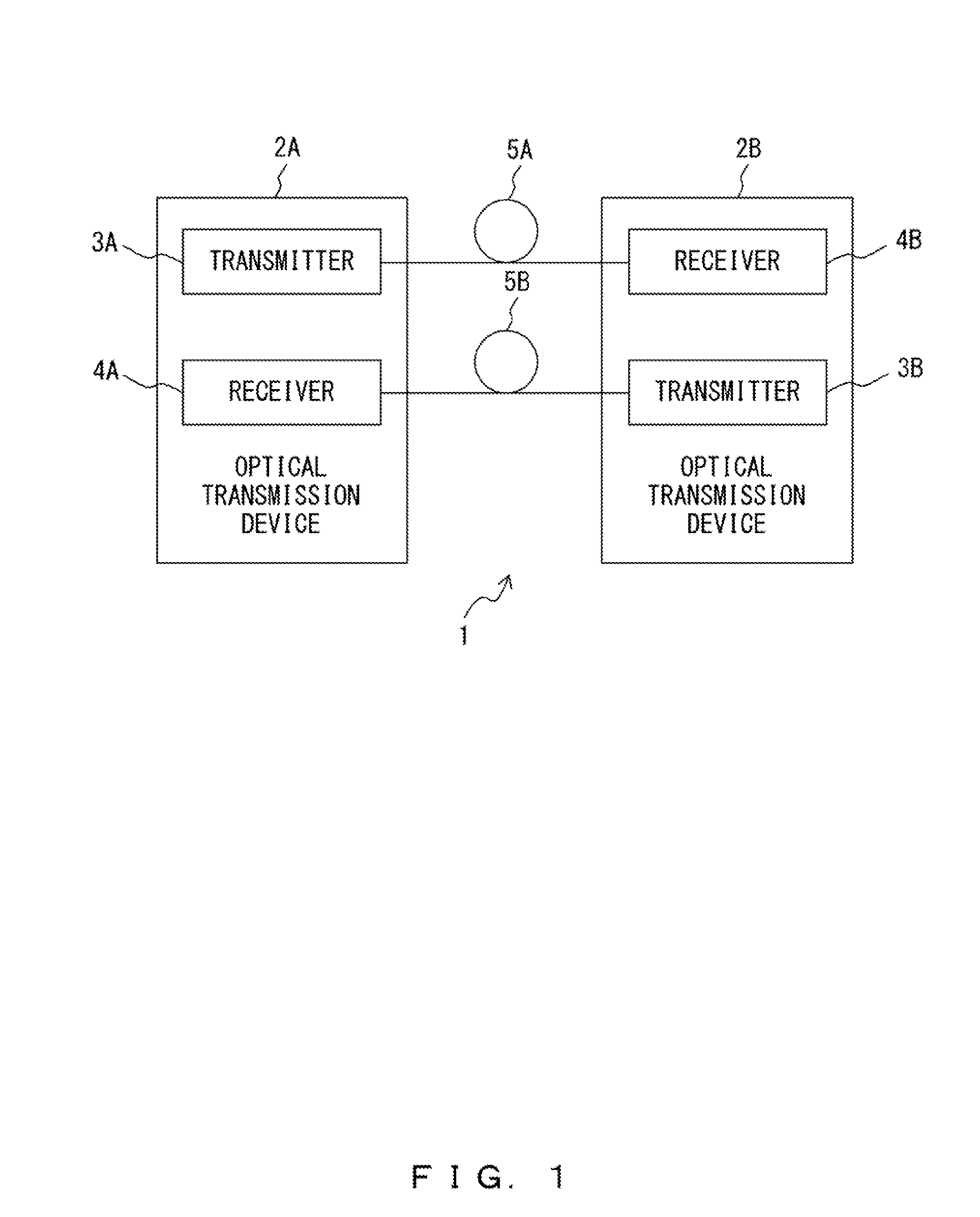
[0106]FIG. 9 illustrates a configuration of an optical transmission system for providing a skew suppression method according to a second embodiment. The optical transmission system according to the second embodiment includes the transmitter 3 illustrated in FIG. 2, the receiver 4 illustrated in FIG. 3, the controller 42, and a chromatic dispersion adder 43. Compared to the first embodiment, the optical transmission system according to the second embodiment is provided with the chromatic dispersion adder 43 instead of the chromatic dispersion adder 41.

[0107]The chromatic dispersion adder 41 optically adds chromatic dispersion to an optical signal. On the other hand, the chromatic dispersion adder 43 electrically adds chromatic dispersion to a data signal for generating an optical signal.

[0108]The chromatic dispersion adder 43 is realized by, for example, a digital filter. When a bit rate of the data signal and a modulation scheme are known in advance, distortion of an optical signal ...

third embodiment

[0110]In the first and second embodiments, the Tx skew and the Rx skew are independently suppressed by sufficiently increasing the chromatic dispersion added to the optical signal. On the other hand, in a third embodiment, the Tx skew and the Rx skew are independently suppressed by sufficiently increasing a differential group delay (DGD) added to the optical signal. DGD is generated by polarization mode dispersion.

[0111]FIG. 10 illustrates simulation results of skew, polarization mode dispersion, and Q factor. The simulations are conducted under substantially the same conditions as in FIG. 4. In the simulations illustrated in FIG. 10, the Tx skew is +9 ps and the Rx skew is also +9 ps. In addition, in the simulations illustrated in FIG. 10, a relationship between a skew compensation amount and Q factor while the DGD of the polarization mode dispersion is changed is calculated.

[0112]In the case where the DGD of the optical transmission line between the transmitter 3 and the receiver ...


PUM


Abstract

A method for suppressing a skew between a first channel and a second channel in an optical transmission system having a transmitter that transmits an optical signal with the first channel and the second channel and a receiver that receives the optical signal, the method includes: controlling dispersion added to the optical signal to be larger than a specified amount; and controlling a delay time of at least one of the first channel and the second channel in the receiver based on a quality of the optical signal monitored in the receiver to suppress the skew between the first channel and the second channel in the receiver.

Description

CROSS-REFERENCE TO RELATED APPLICATION[0001]This application is based upon and claims the benefit of priority of the prior Japanese Patent Application No. 2011-089131, filed on Apr. 13, 2011, the entire contents of which are incorporated herein by reference.FIELD[0002]The embodiments described herein are related to a technique of suppressing skew between channels in an optical transmission system.BACKGROUND[0003]In recent years, a digital coherent receiver has been developed to provide a large-capacity optical transmission system that enables long-haul transmission. A digital coherent receiver, which performs digital coherent reception, includes an optical front-end circuit and a digital signal processor. The optical front-end circuit generates a digital signal indicating a modulated optical signal using local light generated by a local light source. The digital signal includes a plurality of channels (I signal and Q signal respectively indicating an I-component and a Q-component of...

Claims


Application Information

Patent Timeline
IPC IPC(8): H04B10/08H04B10/18H04B10/07H04B10/2507H04B10/2513H04B10/516H04B10/556H04B10/61
CPCH04B2210/254H04B10/5055
Inventor TANAKA, TOSHIKINISHIHARA, MASATO
Owner FUJITSU LTD
Why Eureka
Try Eureka