Location Tracking

a technology of location and tracking, applied in the field of location tracking, can solve the problems of human body, inability to implement universal mapping algorithms to account for the differences between device types, and time-consuming calibration phas

Active Publication Date: 2012-10-18
HERE GLOBAL BV
View PDF12 Cites 93 Cited by
  • Summary
  • Abstract
  • Description
  • Claims
  • Application Information

AI Technical Summary

Problems solved by technology

However, the calibration phase is time-consuming, and obstacles in the coverage area that alter signals disrupt the results.
One common obstacle is human bodies, which may be modeled as large sacks of fluid that absorb energy.
Human bodies are likely less prevalent in the calibration phase than when the system is implemented, which leads to inaccuracies.
Further, the results may be unreliable because any object moved from calibration phase locations can significantly alter the radio map.
Empirical tests have shown determining the current location of a device of brand X when the radio space has been calibrated for a device of brand Y is difficult and universal mapping algorithms to account for the differences among device types may not be feasible.

Method used


Image

  • Location Tracking
  • Location Tracking
  • Location Tracking

Examples


first embodiment

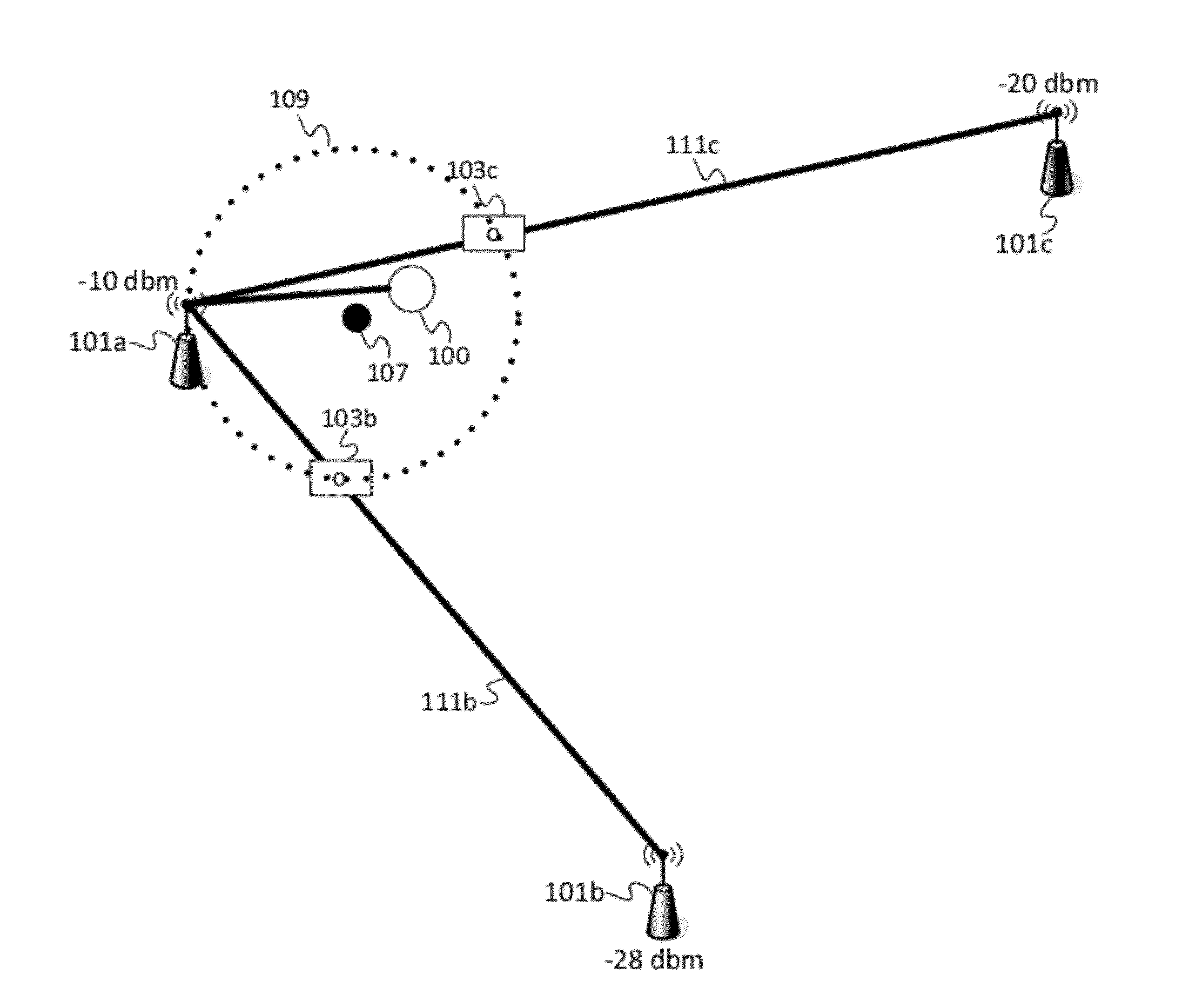
[0033]In the first embodiment, the navigation device 100 may be an RF tag, which is a low cost device that receives signals from the access points 101a-c. The RF tag is a low-energy, embedded system, which may comprise a processor, and a memory storing a protocol stack such as Wi-Fi or Bluetooth low energy (Wife Tag or Bluetooth Tag). The RF tag may receive signal strength data and report the signal strength data to server 120. In this scenario, the server 120 determines the location of the RF tag through communication with the RF tag and may then communicate with the user through another wireless device via text message, email, or another application.

second embodiment

[0034]In the second embodiment, the navigation device 100 performs more of the analysis in the location tracking algorithm. For example, the navigation device 100 may receive signal strength from the access points 101a-c and compare the signal strength to identify the anchor access point and the attractor access points. The navigation device 100 may send an instruction to server 120 to access database 130 for locations of the anchor access point and the attractor access points. The navigation device 100 calculates the pull points between the anchor access point and the attractor access points and estimates a location of the navigation device 100 by averaging the locations of the pull points and the location of the anchor access point.

third embodiment

[0035]In the third embodiment, all instructions for location tracking in the radio space are found on the navigation device 100 and no connection to the network 110 is necessary. The navigation device 100 includes a database with the locations of the access points.

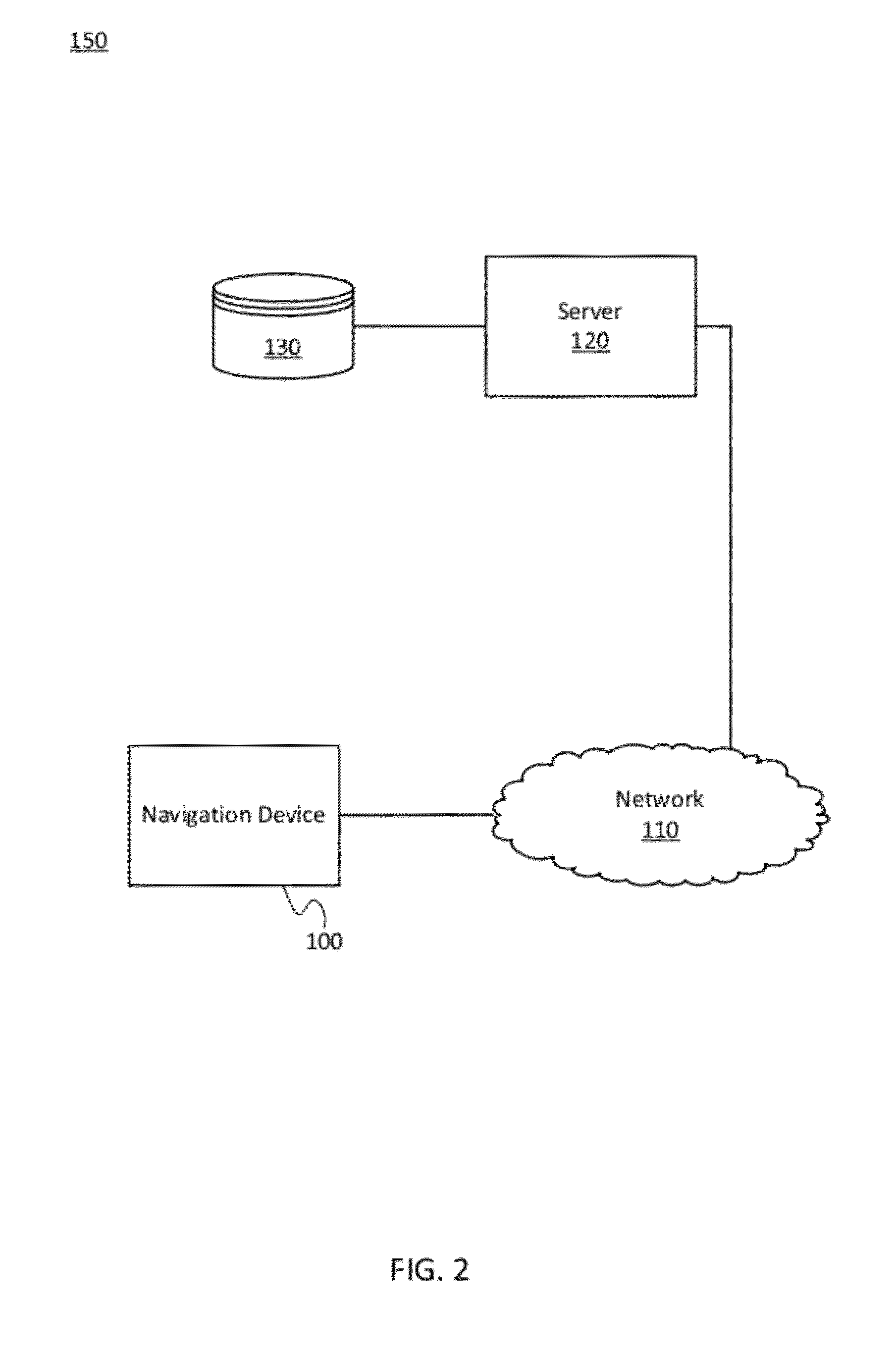
[0036]FIG. 3 illustrates an example of server 120, which may be used in the first embodiment or the second embodiment. The server 120 includes a server controller 300, a communication interface 305 and a memory 301. The server 120 may be in communication with database 130.

[0037]The communication interface 305 may receive the signal strength data of the access points 101a-c from the navigation device 100. The signal strength data may be calculated based on a packet conforming to the 802.11 or Bluetooth standards. For example, the Bluetooth low energy (BLE, 802.15.1, or Bluetooth 4.0) protocol utilizes a small packet size (60-70 bytes) and provides the signal strength data in units such as dbm. The power consumption in BLE, ...


PUM


Abstract

One or more systems, devices, and / or methods for tracking a wireless device are disclosed. For example, a method includes receiving signal strength data for each of a plurality of access points. The signal strength data from the plurality of access points is compared to identify an anchor access point having a highest signal strength. Remaining signal strength data from the plurality of access points are compared to a threshold signal strength to identify at least one attractor access point. A memory is accessed for locations of the anchor access point and the at least one attractor access point. A pull point is calculated along a line from the anchor access point to the at least one attractor access point. A location of the wireless device is estimated as an average of the pull point and the location of the anchor access point.

Description

CROSS-REFERENCE TO RELATED APPLICATION[0001]This application claims the benefit of U.S. Provisional Application No. 61 / 475,360 filed Apr. 14, 2011, which is hereby incorporated by reference in its entirety.BACKGROUND OF THE INVENTION[0002]The present invention relates to location, maps, and / or navigation and, more particularly, to location tracking method(s) and system(s).[0003]Signal strength may be used to determine the location of a device throughout an intended coverage area. Conventional systems require a calibration phase, in which the device is systematically positioned at various points throughout the radio space in order to capture a set of signal strength samples for signals transmitted within range. After signal strength samples have been captured at all the desired calibration points, software may build a “radio map” of the coverage area. The radio map may include signal strength probability densities throughout the coverage area. Once the calibration phase is complete, ...

Claims


Application Information

Patent Timeline
Patent Type & Authority Applications(United States)
IPC IPC(8): H04W24/00
CPCG01S5/0252H04W4/025G01S5/14G01C21/206G01S5/02521
Inventor RIEGER, III, CHARLES J.
Owner HERE GLOBAL BV
Why Eureka
Try Eureka