Method of transforming a doppler velocity dataset into a velocity vector field
- Summary
- Abstract
- Description
- Claims
- Application Information
AI Technical Summary
Benefits of technology
Problems solved by technology
Method used
Image
Examples
Embodiment Construction
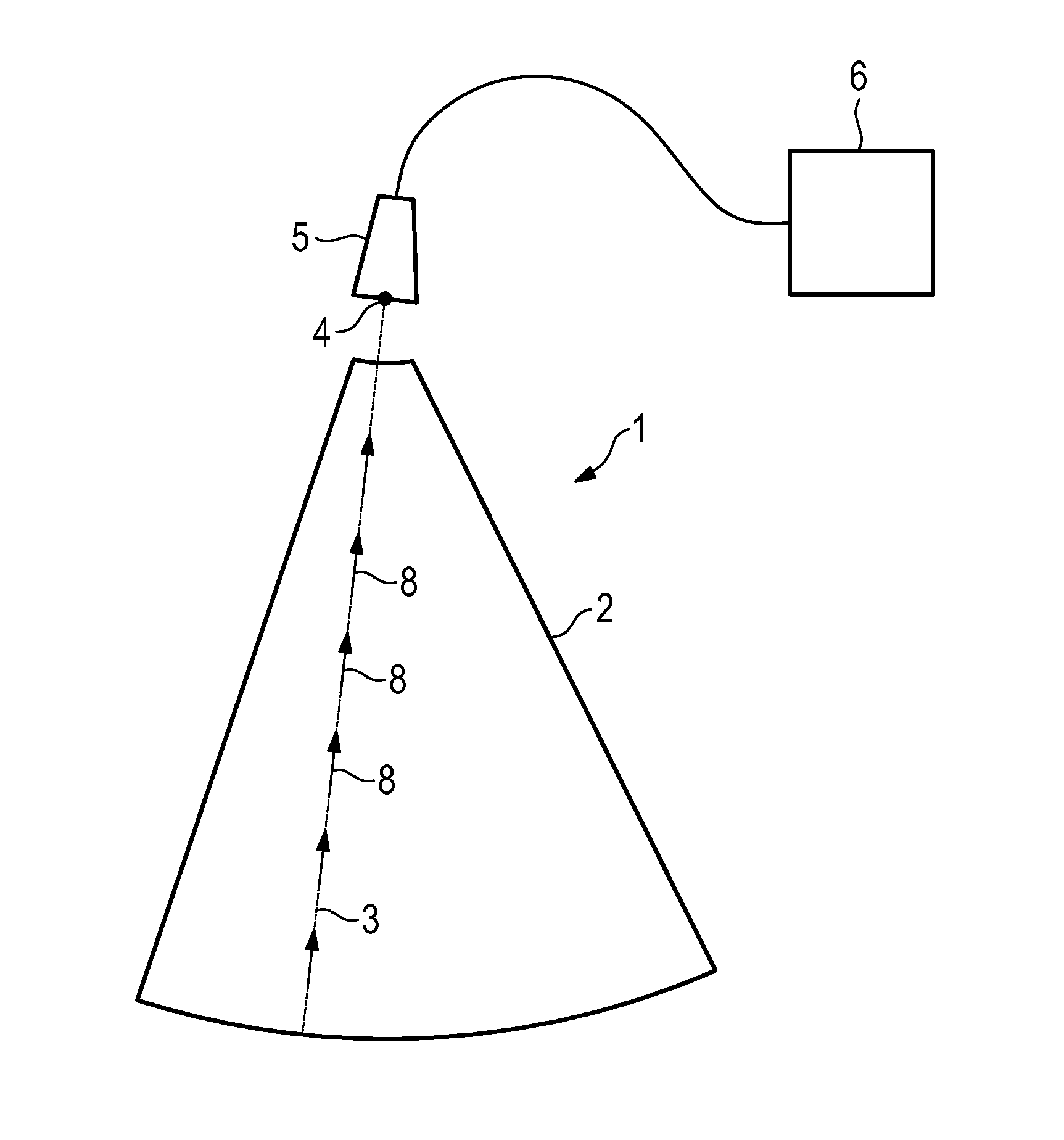
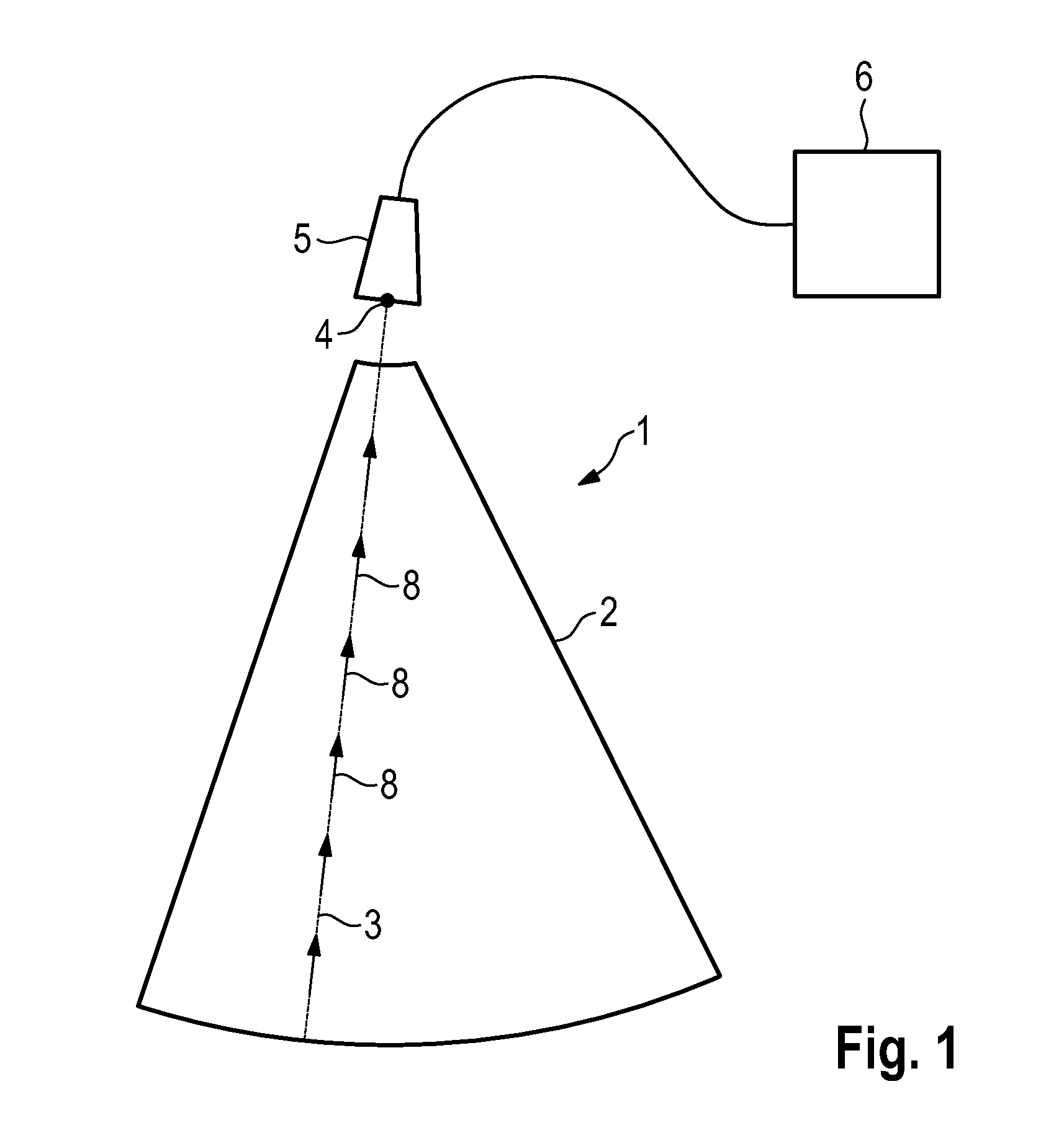
[0051]FIG. 1 is a schematic plan view of a 2D Doppler velocity dataset 1, acquired by means of an ultrasound probe 5 connected to an ultrasound device 6. The conical sector 2 represents the acquisition space or field-of-view, and the Doppler velocity is acquired along all scan-lines 3, which are lines emanating from point 4 on probe 5. One scan-line 3 is shown and a few exemplary Doppler velocity 8 are drawn on top in the shape of arrows.
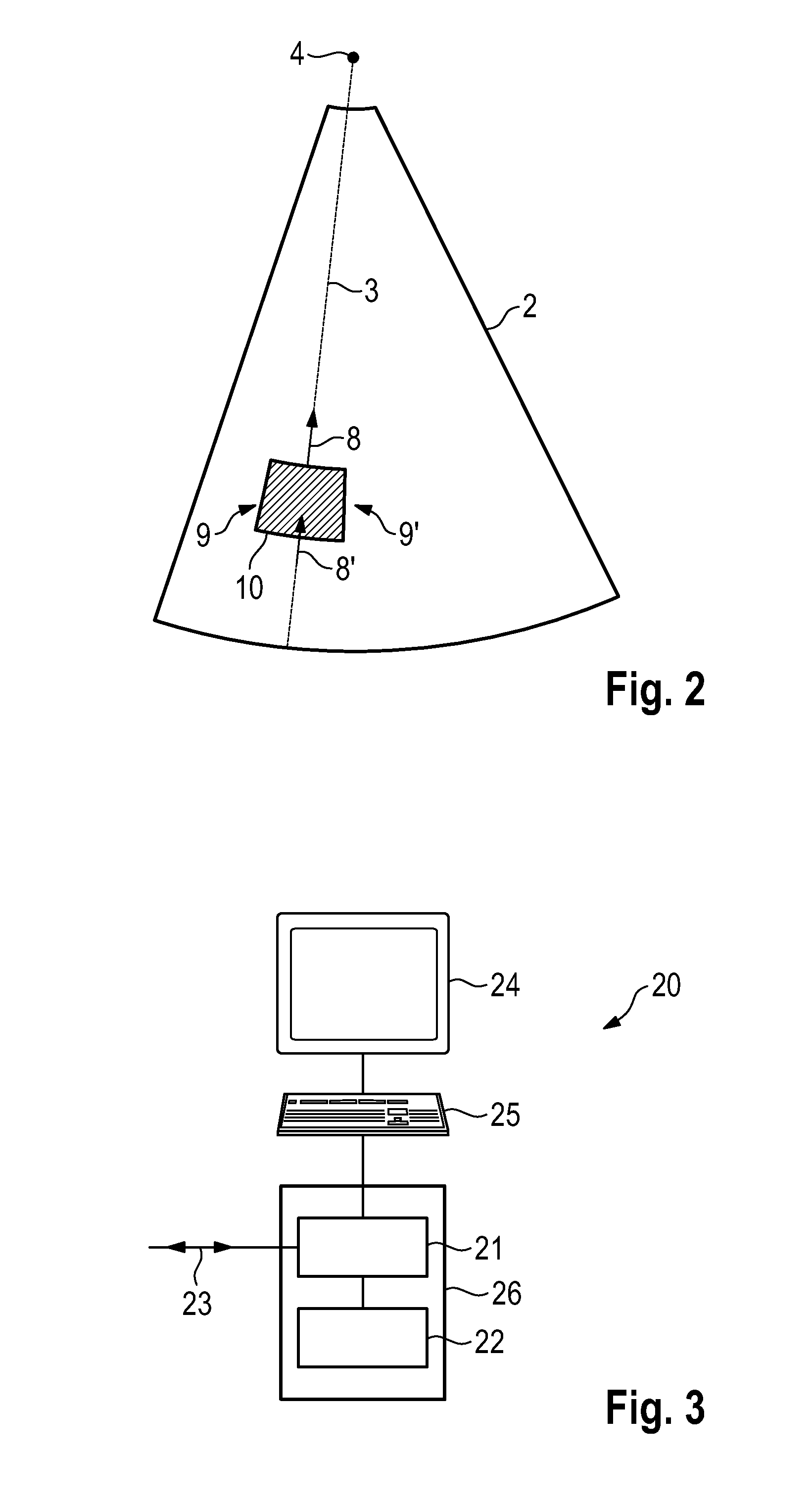
[0052]As stated above, Doppler ultrasound is capable only of measuring the velocity component in the direction of the scan-line. The transverse velocity has to be estimated, which may be done by means of the inventive method.
[0053]FIG. 2 shows the underlying concept of this calculation. The figure shows the same field-of-view 2 and a scan-line 3, as well as two Doppler velocities 8 and 8′. Further shown is a small region 10 at the boundaries of which the Doppler velocities 8 and 8′ have been measured. The mass balance in region 10 imposes that when ...
PUM
 Abstract
Description
Claims
Application Information
 - R&D
- Intellectual Property
- Life Sciences
- Materials
- Tech Scout
- Unparalleled Data Quality
- Higher Quality Content
- 60% Fewer Hallucinations
Browse by: Latest US Patents, China's latest patents, Technical Efficacy Thesaurus, Application Domain, Technology Topic, Popular Technical Reports.
© 2025 PatSnap. All rights reserved.Legal|Privacy policy|Modern Slavery Act Transparency Statement|Sitemap|About US| Contact US: help@patsnap.com


