
System for Supporting Robot Hardware Design and Method Thereof

Active Publication Date: 2012-10-18
KOREA INST OF IND TECH
View PDF6 Cites 12 Cited by
  • Summary
  • Abstract
  • Description
  • Claims
  • Application Information

AI Technical Summary

Benefits of technology

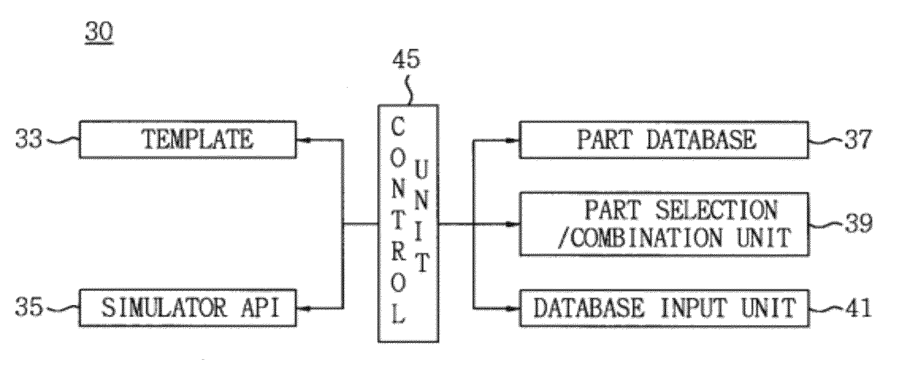
[0017]As described above, according to the system and method for supporting robot hardware design in accordance with the exemplary embodiments of the present invention, it is possible to easily design the hardware of a robot by providing a template having various structures, mechanisms, and power transmission systems of respective modules including a mobile module, an arm module, a head module that constitute the robot.
[0018]Moreover, according to the system and method for supporting robot hardware design in accordance with the exemplary embodiments of the present invention, it is possible to optimally design the robot by determining the specifications of each robot joint through analysis, determining the specification of parts that meet the requirements, and selecting parts.

Problems solved by technology

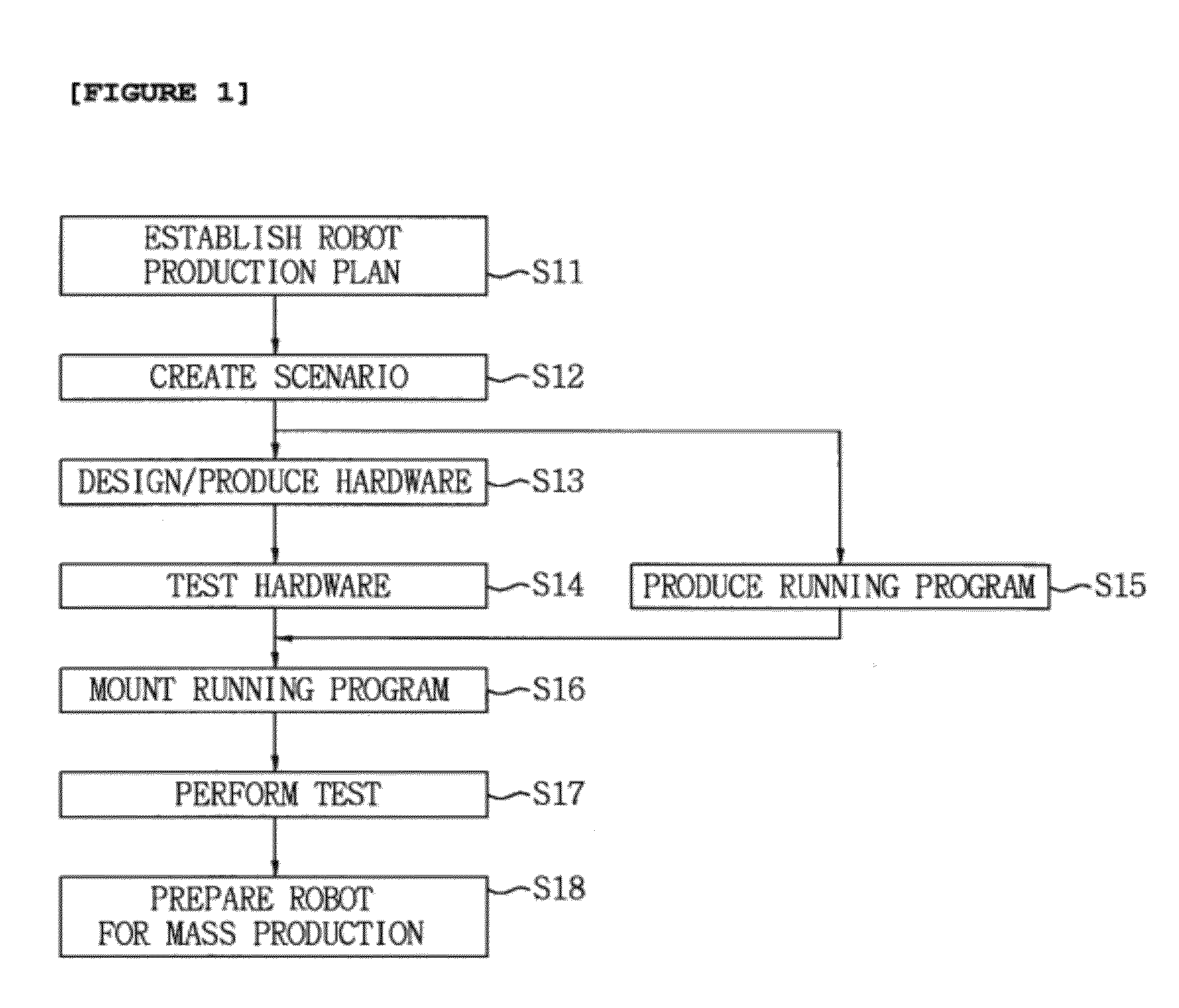
The design / production of the hardware, the production of the running program, etc. generally require a long time while there are some differences depending on the technical difficulties.
In particular, the conventional robot hardware is designed using a design tool such as CAD, for example, which requires specialized design techniques, resulting in reduced accessibility.
Moreover, this design tool is not specialized for the robot design, and thus it is difficult to professionally design the robot only.
Furthermore, there is a lack of standard parts, systematic performance test data, etc. for the robot development, and thus it is also difficult to optimally design the robot using various parts.

Method used


Image

  • System for Supporting Robot Hardware Design and Method Thereof
  • System for Supporting Robot Hardware Design and Method Thereof
  • System for Supporting Robot Hardware Design and Method Thereof

Examples


Embodiment Construction

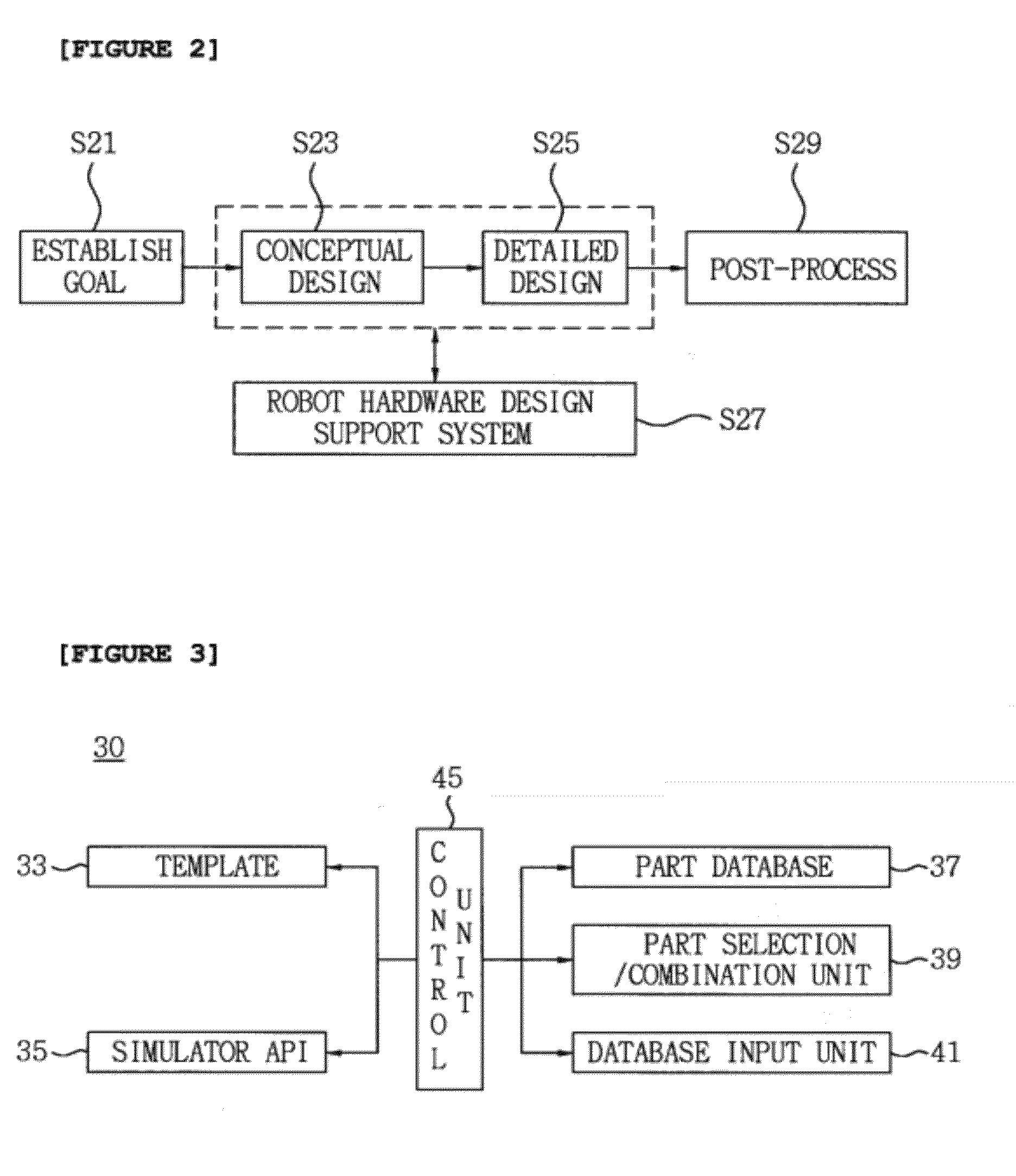
[0024]The above and other objects and novel characteristics of the present invention will be more apparent from the description of the present specification and the accompanying drawings. First, the concept of the present invention will be described with reference to FIG. 2. FIG. 2 is a diagram showing the concept of a robot hardware design support system in accordance with an exemplary embodiment of the present invention.

[0025]As shown FIG. 2, in order to design a robot, a goal in accordance with the purpose and intended use should be established (S21). When the goal of developing the robot is established in the above step S21, general structure and specifications of the robot are determined as a conceptual design (S23). The general structure and specifications determined in the above step S23 are verified through dynamic simulation and reflected in the conceptual design. Then, the specifications of parts are selected as a detailed design, and a combination of parts is recommended ...


PUM


Abstract

The present invention relates to a system and a method for supporting robotic hardware design, and the method comprises: loading a template which has information on the mechanical structure, operating mechanism, power transmission and motion data of robot modules; modifying the information for use in a simulator for further designing the robot modules; analyzing the behavior of each robot module according to respective motion data; applying the resulting data to modify each robot module according to simulation API; and controlling the selection / combination of robot parts for simulator assembly according to API and the resulting templates, databases on which robot parts are required and databases for information on selection / combination of robot parts and assembly of each robot module. The above system and method provide an optimal way to design robot hardware and reduce the time required for robot hardware design.

Description

TECHNICAL FIELD [0001]The present invention relates to robot hardware design support and, more particularly, to a system and method for supporting robot hardware design which can reduce the time and cost of conceptual design and detailed design in the production of a robot when robot modules and platforms are built using common parts.BACKGROUND ART [0002]In general, robots are classified into industrial, medical, space, and submarine robots and applied in various fields. For example, the industrial robots that repeat the same movements are used in the machining industry such as automobile production. In the medical field, a prosthetic hand that drives a motor by myogenic potentials evoked by an armless person's intention, i.e., a command from motor nerve is commercialized. In the field of space development, remote control robots such as moon crawlers have been developed in the USA and Russia.[0003]To design these robots, it is necessary to establish a goal of developing a desired ro...

Claims


Application Information

Patent Timeline
IPC IPC(8): G06F17/50
CPCG06F17/50G05B15/02G05B19/4097G06F30/00
Inventor CHOI, MU SUNGYANG, KWANG WOONGSHIN, EUN CHOLKIM, HONG SEOK
Owner KOREA INST OF IND TECH
Learn More