Exhaust gas sampling device

a sampling device and exhaust gas technology, applied in sampling, measurement devices, instruments, etc., can solve the problems of inability to accurately perform dilution ratios equal or less than 2 times, and difficulty in obtaining a desired dilution rate with accuracy in some cases

Inactive Publication Date: 2012-10-25
HORIBA LTD
View PDF0 Cites 14 Cited by
  • Summary
  • Abstract
  • Description
  • Claims
  • Application Information

AI Technical Summary

Benefits of technology

[0018]According to the present invention configured as described above, it becomes possible to set the dilution rate of the sample gas without being restricted by the flow compensation ranges of the first flowmeter provided on the upstream side of the dilution tunnel and the second flowmeter provided on the downstream side and, in particular, it becomes possible to dilute the sample gas at a low dilution rate.

Problems solved by technology

However, in the configuration of determining the flow rate of a sample gas introduced to the dilution tunnel using the first flowmeter and the second flowmeter, the dilution rate of the exhaust gas is restricted by measurement ranges of the first and second flowmeters so that it is difficult to obtain a desired dilution rate with accuracy in some cases.
That is, in the case where the first and second flowmeters are respectively used in the flow compensation ranges thereof, the minimum value of the dilution rate of the exhaust gas is limited to a double, and therefore there is a problem that dilution ratio cannot be accurately performed at equal to or less than 2 times.

Method used


Image

  • Exhaust gas sampling device
  • Exhaust gas sampling device
  • Exhaust gas sampling device

Examples


Embodiment Construction

[0034]The following describes one embodiment of an exhaust gas sampling device according to the present invention referring to drawings.

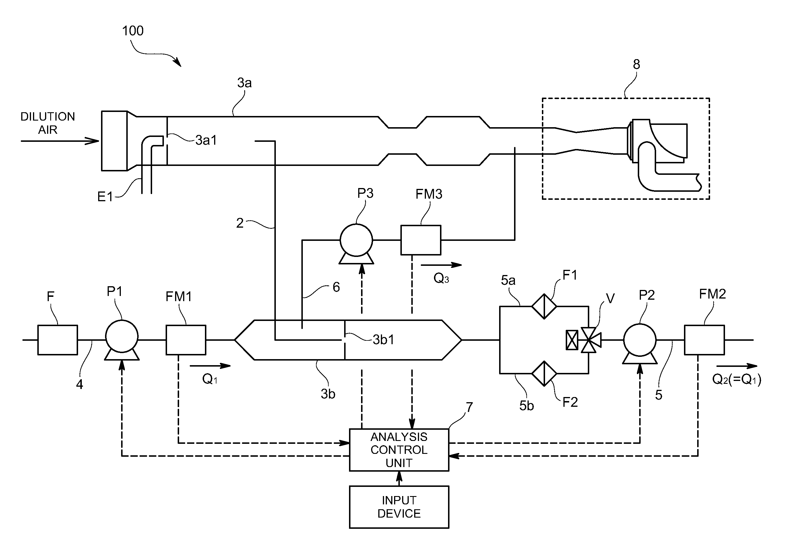
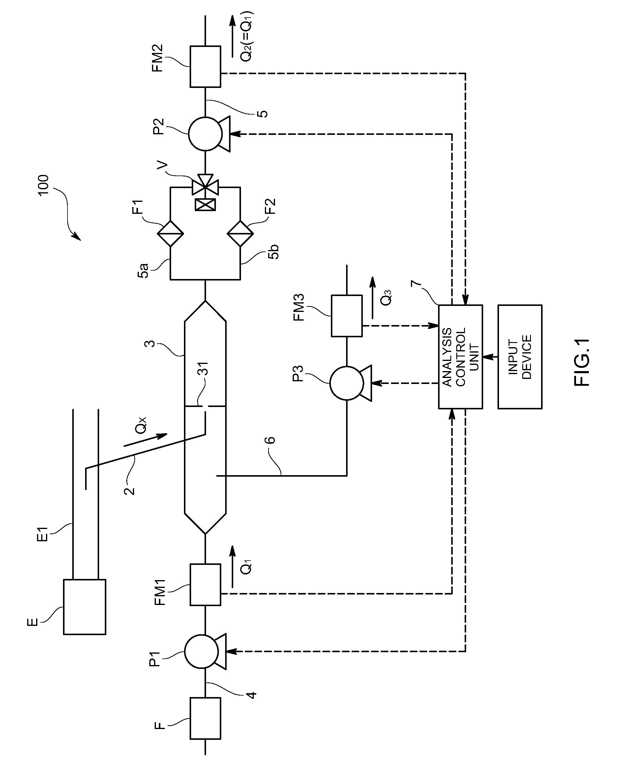
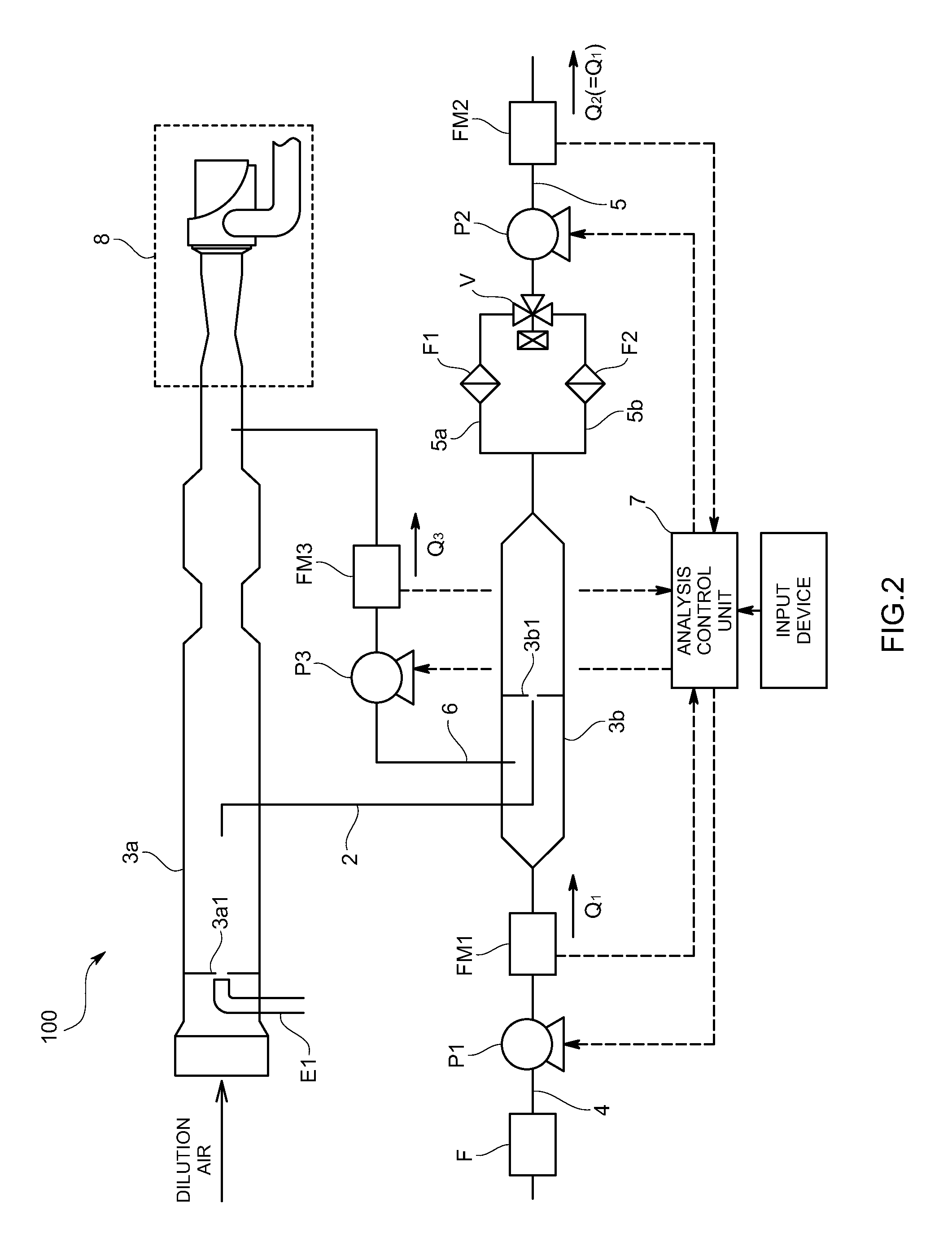
[0035]The exhaust gas sampling device 100 according to the present embodiment is micro-tunnel typed one that divides and collects (sampling) exhaust gas from an exhaust pipe E1 linked to such as a diesel engine E mounted on, e.g., a car so that the exhaust gas is diluted to collect PM contained therein.

[0036]Specifically, as shown in FIG. 1, this device includes: a sampling pipe 2 inserted and connected to an exhaust pipe E1 for sampling a part of the exhaust gas as a sample gas flowing through the exhaust pipe E1; a downstream-side dilution tunnel (referred to as “dilution tunnel” hereinafter in the present embodiment) 3 into which the exhaust gas (sample gas) sampled through the corresponding sampling pipe 2 is introduced so as to be diluted by mixture in a mixing part 31 such as, an orifice; a dilution air flow path 4 connected to an upstream sid...


PUM


Abstract

An engine gas sample device which can set a dilution rate of a sample gas without being restricted by warranty flow ranges of first and second flowmeters. The device makes it possible to dilute the sample gas at a low dilution rate, and is provided with a downstream-side dilution tunnel in which a part of exhaust gas flowing through an exhaust pipe is introduced as sample gas into a mixing part. A dilution gas flow path which is connected to an upstream side of the downstream-side dilution tunnel and includes the first flowmeter FM1, a diluted sample gas flow path which is connected to the downstream side of the downstream-side dilution tunnel and includes the second flowmeter FM2. A dilution gas discharge flow path which is connected to an upstream side of the mixing part in the downstream-side dilution tunnel and includes a third flowmeter FM3.

Description

TECHNICAL FIELD[0001]The present invention relates to an exhaust gas sampling device to be used in measuring PM (Particulate Matter such as soot) contained in exhaust gas for quantitatively analyzing the PM discharged from such as a diesel engine mounted on a vehicle.BACKGROUND ART [0002]As a conventional exhaust gas sampling device, as disclosed in Patent Literature 1, it is configured that a dilution air flow path is connected to an upstream side of a dilution tunnel into which a part of exhaust gas is introduced as a sample gas, wherein the dilution air flow path is provided with a first flowmeter adapted to measure a flow rate (QA) of dilution air for diluting the introduced exhaust gas. Also, a measurement flow path is connected to an downstream side of the dilution tunnel, wherein the measurement flow path is provided with a filter for collecting PM contained in the diluted exhaust gas and a second flowmeter adapted to measure a flow rate (QB) of the diluted exhaust gas passin...

Claims


Application Information

Patent Timeline
Patent Type & Authority Applications(United States)
IPC IPC(8): G01F1/00
CPCG01N1/2252G01N2001/2255
Inventor TAKAHASHI, YASUSHI
Owner HORIBA LTD
Why Eureka
Try Eureka