Method for reinforcing rail by laser and auxiliary heat source efficient hybrid cladding

a technology of laser and auxiliary heat source, applied in the field of material processing, can solve the problems of rail wear, rail corrosion, rolling contact fatigue, etc., and achieve the effects of reducing the cooling rate, avoiding cracking and spalling of the metal cladding coating, and reducing the temperature gradien

Pending Publication Date: 2020-06-25
WUHAN HIVALUE INTELASER LTD +2
View PDF0 Cites 12 Cited by
  • Summary
  • Abstract
  • Description
  • Claims
  • Application Information

AI Technical Summary

Benefits of technology

[0022]① The laser and the auxiliary heat source simultaneously apply on a region to be cladded of a rail surface; the high-energy laser beam enables rapid fusion of a cladded coating material and a thin-layer material on the rail surface to form a molten pool; and the auxiliary heat source performs synchronous preheating and post-heating on the laser molten pool, a heat-affected zone and a surface layer of the rail substrate to reduce a temperature gradient between the laser molten pool, the heat-affected zone and the rail substrate, thereby reducing the cooling rate, and avoiding cracking and spalling of the metal cladded coating and the heat-affected zone at a high laser scanning rate.
[0023]② Through adjusting the relative position of the laser and the auxiliary heat source, the laser processing power, the laser scanning rate, and the heating temperature of the auxiliary heat source to the rail, a temperature cycle curve of the heat-affected zone can be reasonably controlled such that a cooling time of the heat-affected zone is larger than a critical cooling time of transformation from austenite to pearlite in the CCT curve or the TTT curve, thereby meeting critical conditions of complete transformation from austenite to pearlite, and allowing the heat-affected zone to be transformed into a fine lamellar pearlite structure which has an interlamellar spacing less than or equal to that of the rail substrate and has a hardness between those of the cladded coating and the rail substrate, so that mechanical properties between the cladded coating, the heat-affected zone and the rail substrate are reasonably matched, the hardness curve is smooth, and the overall fatigue performance is good.
[0024]③ Compared with other methods such as plasma arc and electric arc, the laser energy density is high, the heat-affected zone is small, the martensite structure in the heat-affected zone can be eliminate while the heating width and depth of the induction coil and other auxiliary heat sources are just larger than the heat-affected zone width, so that the overall heat input is small resulting in small processing residual stress and deformation, and high stability of the rail; the device has good flexibility and high processing precision, and can repair rails with different degrees of damage.
[0025]④ The cladded coating has low dilution rate, especially for a thinner cladded coating. When the thickness of the cladded coating is less than 0.5 mm, the dilution rate of the coating is less than 5%, which can ensure the wear resistance and corrosion resistance of the cladded coating.
[0026]⑤ Due to the combination of the auxiliary heat source, the energy required to form the molten pool is greatly reduced. When the laser power is 1-20 kW, the deposition rate of the cladded coating can reach 10-250 g / min, and the scanning speed reaches 0.4-30 m / min. Compared with the pure laser cladding process, the deposition efficiency is increased by 3-15 times.
[0027]The present disclosure has strong versatility, and can efficiently prepare a wear-resistant, corrosion-resistant and fatigue-resistant cladded coating with uniform composition and matched mechanical properties directly on the rail surface, and can also repair a locally damaged rail. The hardness distribution curve of the reinforced or repaired rail along the depth direction is smooth, the mechanical properties of the cladded coating, the heat-affected zone and the substrate are matched with each other, and the overall fatigue performance is good, so that the coating spalling does not occur during the service. Meanwhile, various process components used in the method in the present disclosure have high integration degree and are easy to integrate with related processing platforms, and the method can be used for both a fixed laser processing machine to perform off-line processing and mobile laser processing equipment (e.g., a mobile laser processing vehicle) to perform on-line reinforcement or repair at the railway site.

Problems solved by technology

With the increase of railway transportation volume, train speed and axle load, damage problems such as rail wear, rolling contact fatigue and rail corrosion of rails are becoming more and more prominent.
The welding layer and the rail substrate are metallurgically bonded, but in this method, the heat input and heat-affected zone are large, resulting in that the microstructure and performance uniformity of the surfacing layer are poor, and the martensite structure is easily induced inside the rail substrate.
However, with the rapid heating and rapid cooling effect of the laser, high-carbon acicular martensite structure may be generated in the heat-affected zone of the rail.
The martensite structure has high hardness, but low toughness, which may easily cause the rail breakage.
In addition, since the cladded coating and the heat-affected zone have a high cooling rate and a large temperature gradient relative to the rail substrate at a high laser scanning rate, cracks may be easily generated in the cladded coating and the heat-affected zone, which affects the safe service of the train.
However, this method does not consider how to reduce and avoid the martensite phase transformation in the heat-affected zone when preparing a cladded coating on a large high-carbon steel substrate (such as a rail), as well as technical problems such as matching of mechanical properties of the cladded coating, the heat-affected zone and the substrate in a specific service environment (rolling rail contact).

Method used


Image

  • Method for reinforcing rail by laser and auxiliary heat source efficient hybrid cladding
  • Method for reinforcing rail by laser and auxiliary heat source efficient hybrid cladding
  • Method for reinforcing rail by laser and auxiliary heat source efficient hybrid cladding

Examples


embodiment 1

[0048] on-line laser and induction post-heating efficient hybrid cladding at the railway site

[0049]In this embodiment, the service rail is efficiently reinforced or repaired at the railway site, in which induction heating acts as an auxiliary heat source, and an industrial manipulator or a three-dimensional motion axis is used as a machining motion and position control unit. A region to be cladded of a rail surface is heated with the heating temperature and time controlled by an induction heating device and a temperature control part. The induction heating device includes an induction power supply and an induction coil, and the temperature control part includes an infrared thermometer and a temperature controller, in which the induction coil is connected to the induction power supply, the infrared thermometer is connected to the temperature controller, and the temperature controller is connected to the induction power supply via a data line. A detection signal of the infrared thermo...

embodiment 2

[0059]Embodiment 2: on-line laser, induction preheating and induction post-heating efficient hybrid cladding at the railway site

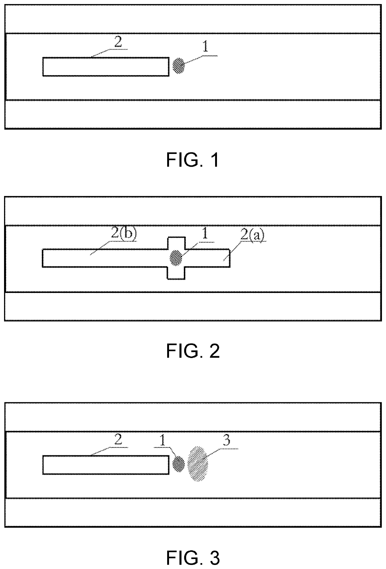
[0060]In this embodiment, the service rail is efficiently reinforced or repaired at the railway site, in which induction heating acts as an auxiliary heat source, the induction heating control part is the same as that in Embodiment 1, and an industrial manipulator or a three-dimensional motion axis is used as a machining motion and position control unit. The laser spot is focused in the middle of the induction coil, as shown in FIG. 2. Basic implementation steps for preparing a metal cladded coating on a rail surface by laser, induction preheating and induction post-heating hybrid cladding are as follows.

[0061](1) Select nickel-based alloy powder as cladding material, the main chemical compositions (Wt. %) of which are: (0.01-0.50) C, (20-30) Cr, (5-10) W, (3-5) Si, (0-3) B, (5-10) Fe and Ni balance.

[0062](2) Polish a region to be cladded of a rail surface ...

embodiment 3

[0070] off-line laser, induction heating and oxyacetylene flame (or propane torch) heating efficient hybrid cladding on a rail surface

[0071]In this embodiment, off-line reinforcement or repair is performed on the rail, in which induction heating and oxyacetylene flame (or propane torch) act as the auxiliary heat source. The laser spot is focused in front of the induction coil, and the oxyacetylene flame (or propane torch) preheats a rail surface to be cladded, as shown in FIG. 3. The laser and the induction coil move in the same direction at the same speed, and the induction heating synchronously preheats the laser molten pool and the heat-affected zone of the rail. The basic implementation steps are as follows:

[0072](1) Select cobalt-based alloy powder as cladding material, the main chemical compositions (Wt. %) of which are: (0.01-0.5) C, (20-35) Cr, (1-10) Ni, (1-3) Si, (5-15) W, (0-3) B, (0.5-2) Mn and Co balance.

[0073](2) Polish a region to be cladded of a rail surface to remov...


PUM

PropertyMeasurementUnit
temperatureaaaaaaaaaa
widthaaaaaaaaaa

Abstract

The disclosure discloses a method for reinforcing a rail by laser and auxiliary heat source efficient hybrid cladding. The laser and the auxiliary heat source simultaneously apply on a region to be cladded of a rail surface. The laser serves as a main heat source to enable simultaneous and rapid fusion of an added metal powder and partial substrate material in the rail surface to form a molten pool. The auxiliary heat source moves with the laser heat source in the same direction at the same speed, and performs synchronous preheating and/or post-heating on the laser molten pool, the heat-affected zone and the surface layer of the rail substrate to reduce the temperature gradient, thereby reducing the cooling rate, and avoiding martensite transformation and cracking in the heat-affected zone.

Description

BACKGROUNDTechnical Field[0001]The present disclosure belongs to the field of material processing, and particularly relates to a method for efficiently preparing a metal cladded coating on a rail surface by laser and auxiliary heat source hybrid cladding. The method can improve the wear resistance and contact fatigue performance of the rail, solve the problems of poor railway shunt, and repair the damaged rail.Description of Related Art[0002]China's rail transit has developed rapidly, and by the end of 2016, the national railway operation mileage has reached 124,000 kilometers. With the increase of railway transportation volume, train speed and axle load, damage problems such as rail wear, rolling contact fatigue and rail corrosion of rails are becoming more and more prominent. The damage of the rail mainly occurs on the surface, and thus, the preparation of the coating on the surface of the rail is of great significance for extending its service life.[0003]Thermal spraying, electro...

Claims


Application Information

Patent Timeline
Patent Type & Authority Applications(United States)
IPC IPC(8): C21D1/09C21D9/04C23C24/10
CPCC21D9/04C21D2211/009C21D1/09C23C24/106C21D2211/00C23C24/10
Inventor ZENG, XIAOYANMENG, LIWANG, DENGZHIHU, QIANWUGUO, PINGHUAXU, XIAOHUANIU, LI
Owner WUHAN HIVALUE INTELASER LTD
Why Eureka
Try Eureka