Immobilization Device

a technology of immobilization device and immobilization position, which is applied in the field of human medicine or medical research, can solve the problems of insufficient fixation of the body, inability to restrict or define the position, and inability to repeat the immobilization precisely the same location, and achieves the effects of high degree of protection, simple construction and application

Active Publication Date: 2012-10-25
ISYS MEDIZINTECHN
View PDF15 Cites 31 Cited by
  • Summary
  • Abstract
  • Description
  • Claims
  • Application Information

AI Technical Summary

Benefits of technology

[0030]The invention is therefore based on the object of providing a device for immobilization which avoids the aforementioned disadvantages, is simple in construction and application, and therefore protects the patient to a high degree. The device additionally allows the exact attachment of calibration points (so-called markers) and optimum accessibility to operation regions.
[0031]An essential feature in this case is an adhesive layer, by which stable “gluing” of the molding element onto the human body is made possible. This can be achieved using a spray adhesive or an adhesive film, so that after a cover band is pulled off, it is possible to press or “model” on the adhesive layer. The molding element is still soft, so that exact adaptation can occur. The molding element is only solidified and “hardened” into a dimensionally-stable molding element having stable form after application of vacuum thereto.
[0032]By means of a locking a pivot arm, the immobilized body can be additionally fixed in relation to the baseplate of an intervention or operating table, a compression of the body being achieved—if desired—by light pressure. A preferred baseplate, a carbon adapter plate attached to the molding element is x-ray transparent and increases the stability of the entire device through the high stiffness.
[0033]After completing immobilization and application of a sterile covering, a medical intervention (i.e., an operation) (optionally having robot support) can occur in the operating room window, for example. The robot is preferably mechanically coupled to the molding element via the baseplate, i.e., geometrically fixed. Alternatively, a mini-robot can also be directly attached on the molding element, e.g., via a carbon adapter plate. Markers for imaging methods or navigation can also be reproducibly attached. Since it is not simple gluing at spots, but rather a large-area, ergonomic adhesion of an additionally flexible, then rigid molding element, maximum surface contact with high retention forces at maximum comfort results.

Problems solved by technology

However, the following points are some of the disadvantages of this approach:
After removal of the retaining elements (bands), repeated immobilization in precisely the same location is virtually impossible, which is disadvantageous in particular in the case of stereotactic operations and in radiation therapy;
The body is not sufficiently fixed; particularly in the lateral direction; position cannot be restricted or defined sufficiently.
The method is only applicable to specific mountings of the patient and obstructs medical operations;
Immobilization of the soft tissue parts (muscles, ligaments, connective tissue) is practically impossible.
In this method, it is disadvantageous that:
In the case of uncooperative patients, sufficient immobilization is practically impossible;
Precise molding is also not possible, since in practice the mattress cannot be applied precisely to all body parts;
Pressure points often arise due to wrinkling or excessively strong contact pressure, which can result in tissue injuries particularly in sedated patients.
In this case, it is disadvantageous that:
The system is complex, not easy to handle, and difficult to transport;
In the case of interventions which require a high level of asepsis or even sterility, the air stream of the vacuum pump represents a hazard (bacteria entrainment);
Higher connecting forces and therefore improved molding and immobilization are not possible, because injuries (e.g., reduced blood perfusion, effusion of blood) may arise due to excessively high and long-lasting pressures;
In the event of failure of the vacuum, the connection is lost.
The method is complex overall and is hardly practicable in particular for radiological / surgical interventions.
In addition, these methods also entail substantial financial or chronological outlay and are therefore only used for long-term applications.

Method used


Image

  • Immobilization Device
  • Immobilization Device
  • Immobilization Device

Examples


Embodiment Construction

[0043]The following description is provided to enable any person skilled in the art to make and use the invention and sets forth the best modes contemplated by the inventor of carrying out his invention. Various modifications, however, will remain readily apparent to those skilled in the art, since the general principles of the present invention have been defined herein specifically to provide a device for immobilization of the human body for medical and related applications.

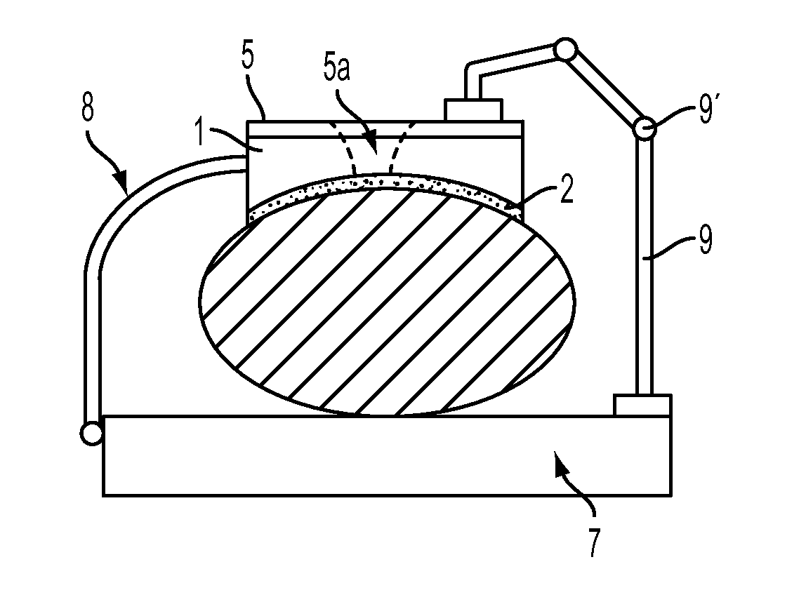
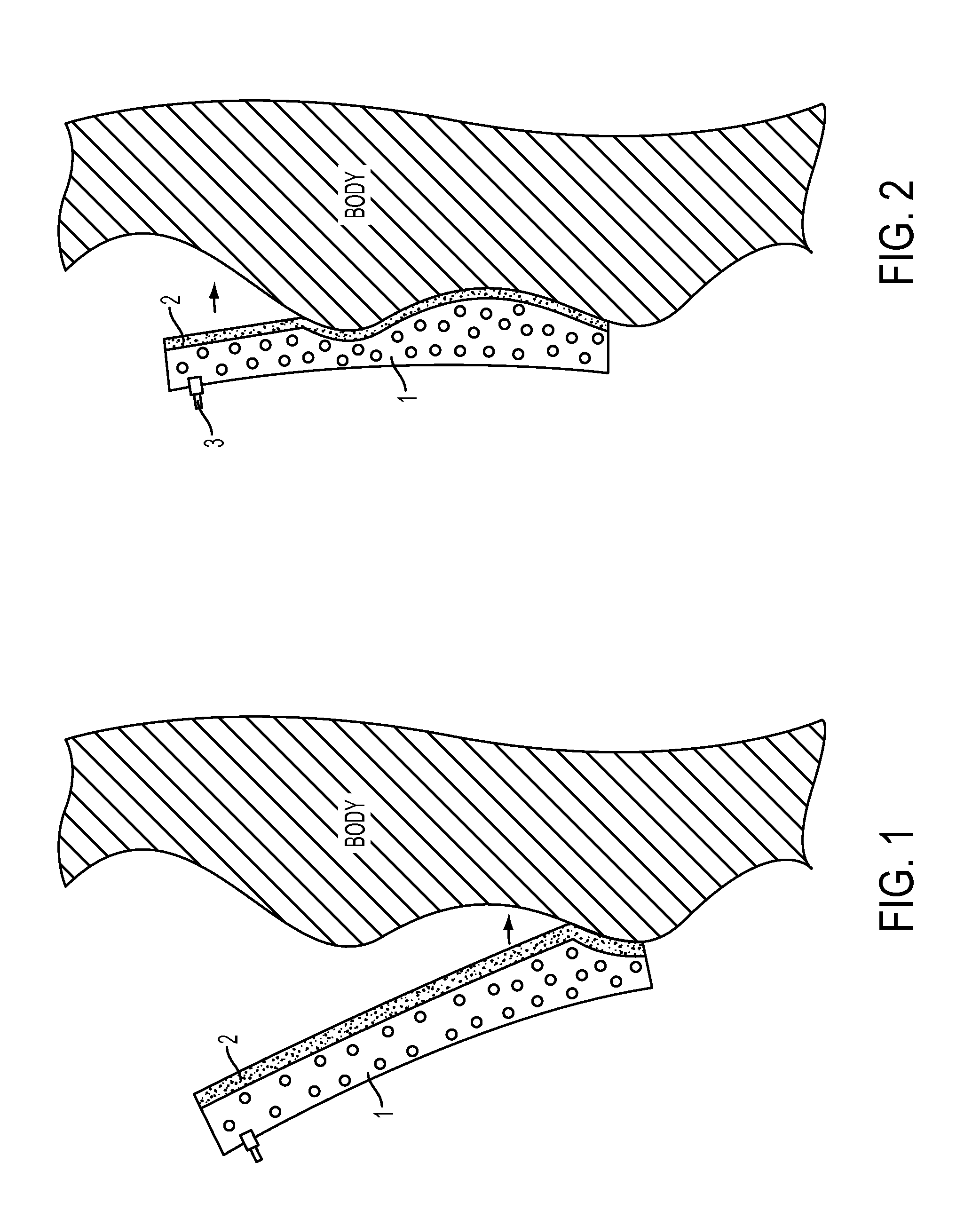
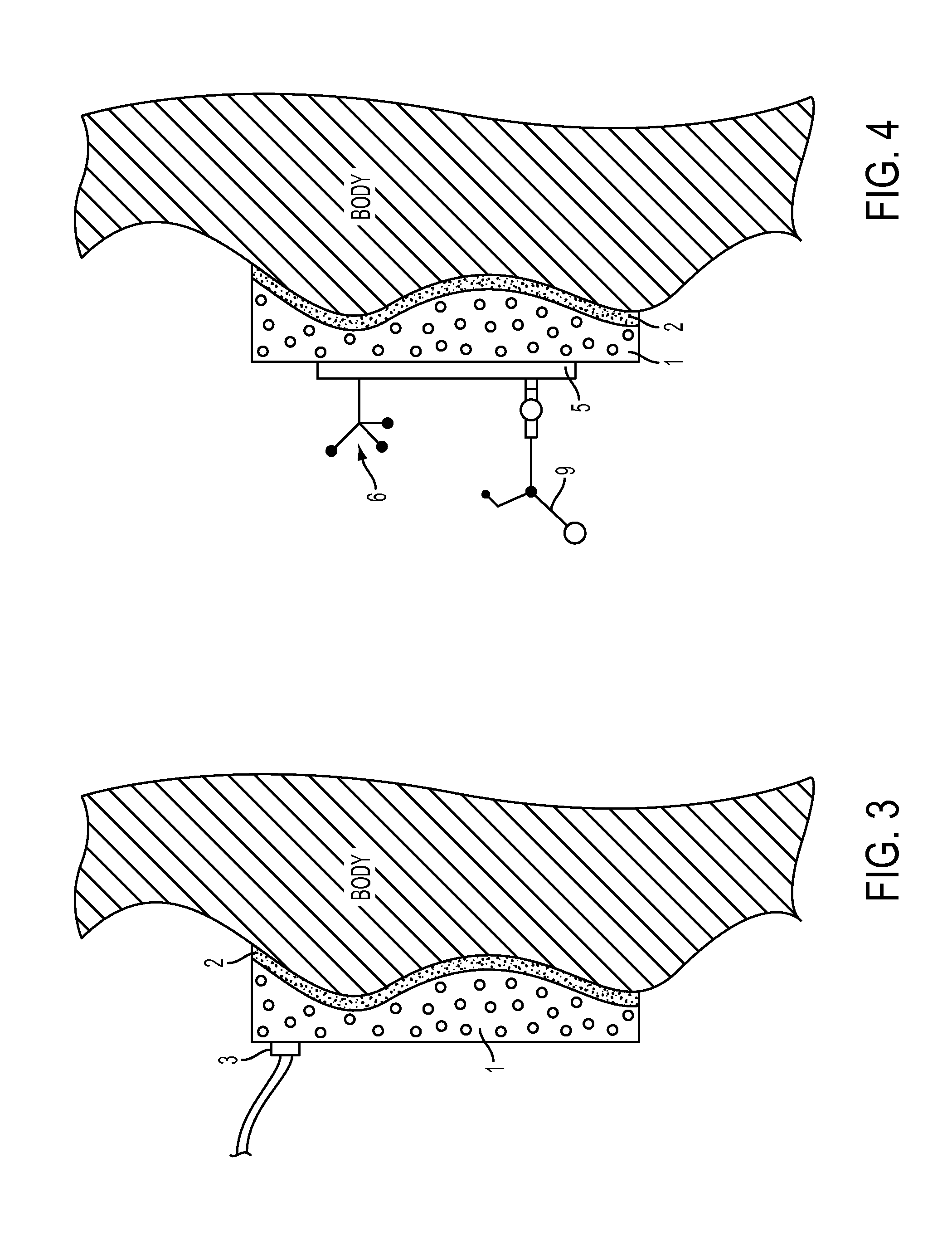
[0044]The device for fixation of the human body or of body parts comprises a molding element 1, which is positionable on the body surface (shown shaded; a back part here, for example) (FIG. 1). This is performed using an adhesive layer 2, which is connected to the molding element 1, e.g., an inner adhesive film is glued on and optionally has a carrier layer to an outer adhesive film, which is pressed against the skin of the body. The adhesive layer 2 can also be formed by a spray adhesive, which is sprayed onto ...


PUM


Abstract

A device for immobilizing a patient for a medical test or operation includes a molding element that is convertible from a flexible, elastic form to a rigid form by the application of a vacuum. The molding element is attached to the patient by an elastic layer while in the flexible, elastic form where it conforms to the contours of the patient's body. Then the molding element is converted to its rigid form thereby immobilizing the patient. Auxiliary devices can be attached to the immobilizing device and these devices, such as a pivot arm suspension can be used to fix the immobilized patient to an operating table.

Description

CROSS-REFERENCE TO PRIOR APPLICATIONS[0001]This application claims the priority of German Utility Model Application No. 20 2011 005 573.6, filed 21 Apr. 2011.U.S. GOVERNMENT SUPPORT[0002]Not ApplicableAREA OF THE INVENTION[0003]The invention relates to a device for reliable immobilization of the human body or parts of the human body, in such uses as medical target devices, markers, and / or surgical instruments for image-guided, minimally invasive operating methods being fixed reliably. “Immobilization” is to be understood in this case in the medical meaning as also including the fixing in place, splinting, positioning, repositioning, compression, or casting of the human body.DESCRIPTION OF THE BACKGROUND OF THE INVENTION[0004]In many fields of human medicine or medical research, secure fixing / immobilization / splinting or compression and / or molding of the patient or parts of the patient or the (mechanical) attachment of devices or appliances is necessary. This is of particularly great ...

Claims


Application Information

Patent Timeline
Patent Type & Authority Applications(United States)
IPC IPC(8): A61B19/00
CPCA61B6/0428A61B6/0492A61B19/203A61B19/54A61B2017/00951A61B2017/3407A61B2019/464A61B2019/5483A61B2019/5491A61B2017/00566A61B2019/205A61B90/17A61B90/14A61B90/39A61B2090/064A61B2090/3983A61B2090/3991
Inventor VOGELE, MICHAEL
Owner ISYS MEDIZINTECHN
Why Eureka
Try Eureka