Multi-channel flat-tube serpentine heat exchanger and heat exchange apparatus

a heat exchanger and multi-channel technology, applied in lighting and heating apparatus, tubular elements, stationary conduit assemblies, etc., can solve the problems of increasing the working hours and cost of soldering and assembly, deteriorating water-proof and dust-proof effect of the conventional heat exchanger, and reducing the number of parts and production costs. , the effect of reducing the working hours

Inactive Publication Date: 2012-10-25
COOLING HOUSE
View PDF17 Cites 25 Cited by
  • Summary
  • Abstract
  • Description
  • Claims
  • Application Information

AI Technical Summary

Benefits of technology

[0024]According to the present invention, a flat pipe is configured to have a plurality of bending sections and a plurality of connecting sections each connecting adjacent two bending sections, and the fin set is connected between the two connecting sections. Thus, unlike the prior art in which the gaps between the copper pipes and the though holes of the fins as well as the parts between the copper curved pipe and adjacent two copper pips have to be soldered respectively, the present invention greatly reduces the working hours for soldering and assembly, and in turn reduces the number of parts and the production cost. On the other hand, since the number of soldering parts is much less than that in prior art, the working fluid in the heat exchanger of the present invention may not escape easily, so that the present invention has an increased yield rate, durability and reliability.
[0025]According to the present invention, since the flat pipe is connected to the fin set, and the contact surfaces between the flat pipe and the fin set are planar surfaces, the present invention has a larger external contact area. Further, the interior of the flat pipe is provided with a plurality of channels separated from each other. These separated channels can further increase the internal heat-exchange area between the working fluid and the inner walls of the flat pipe, thereby increasing the heat-exchange efficiency of the whole heat exchanger.

Problems solved by technology

However, the conventional heat exchanger has the following problems.
Thus, it can be understood that there are so many soldering parts (even up to hundreds of soldering parts) in the conventional heat exchanger, which inevitably increases the working hours and cost for soldering and assembly.
Further, since the gaps may exist between the copper pipes and the through holes if they are not soldered tightly, the water-proof and dust-proof effect of the conventional heat exchanger will be deteriorated greatly.
According to the above, since there are so many soldering parts in the conventional heat exchanger, the working fluid filled in the heat exchanger may escape and the performance of the heat exchanger will deteriorate if any one of the soldering parts cracks.
Therefore, the conventional heat exchanger has a low yield rate and poor reliability.
Thus, the thermal contact area inside and outside the conventional heat exchanger is not large enough, which restricts the heat-exchange efficiency thereof.

Method used


Image

  • Multi-channel flat-tube serpentine heat exchanger and heat exchange apparatus
  • Multi-channel flat-tube serpentine heat exchanger and heat exchange apparatus
  • Multi-channel flat-tube serpentine heat exchanger and heat exchange apparatus

Examples


Embodiment Construction

[0036]The detailed description and technical contents of the present invention will become apparent with the following detailed description accompanied with related drawings. It is noteworthy to point out that the drawings is provided for the illustration purpose only, but not intended for limiting the scope of the present invention.

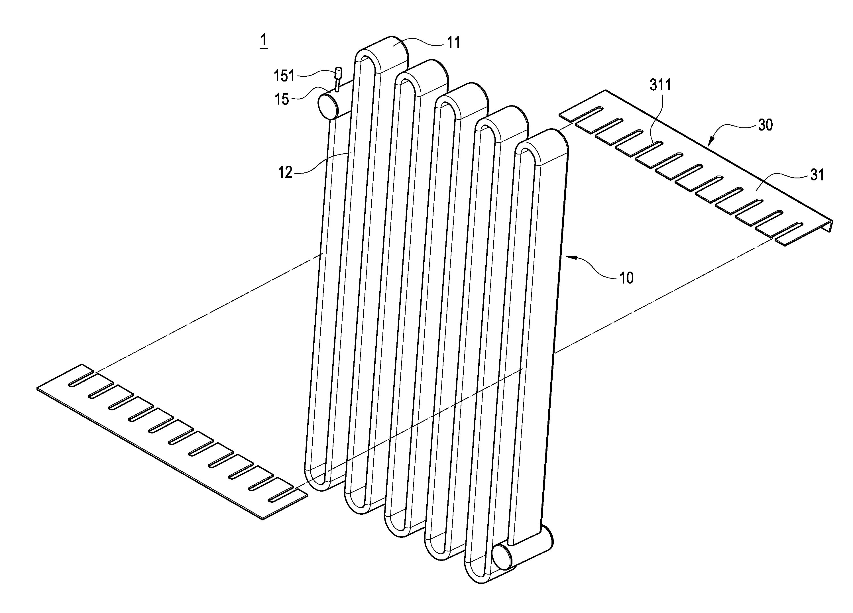
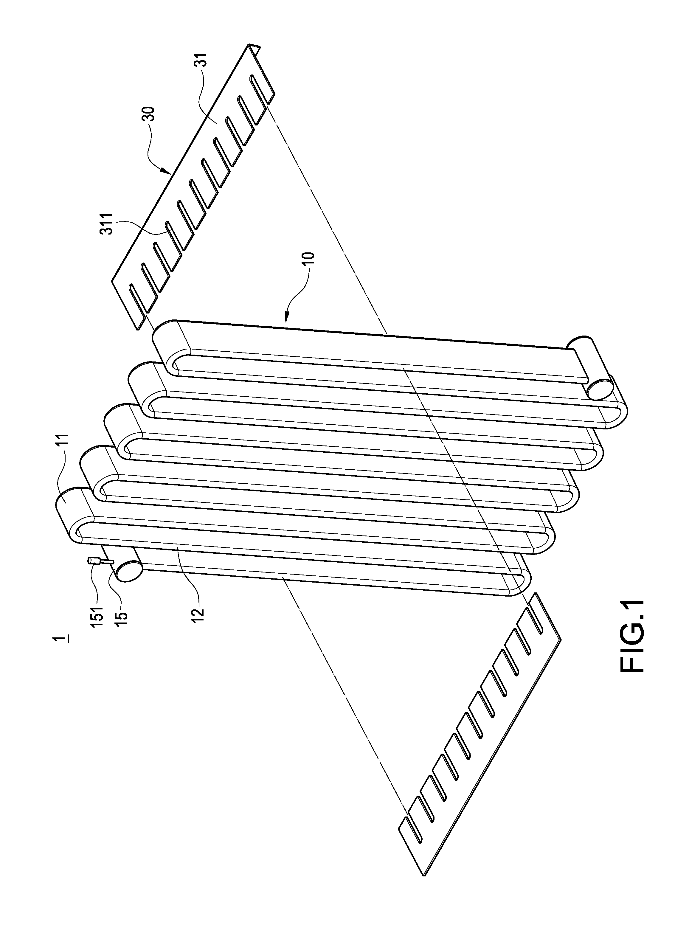
[0037]Please refer to FIGS. 1 to 4. The present invention relates to a multi-channel flat-tube serpentine heat exchanger 1, which includes a flat pipe 10, a fin set 20 and a divider assembly 30.

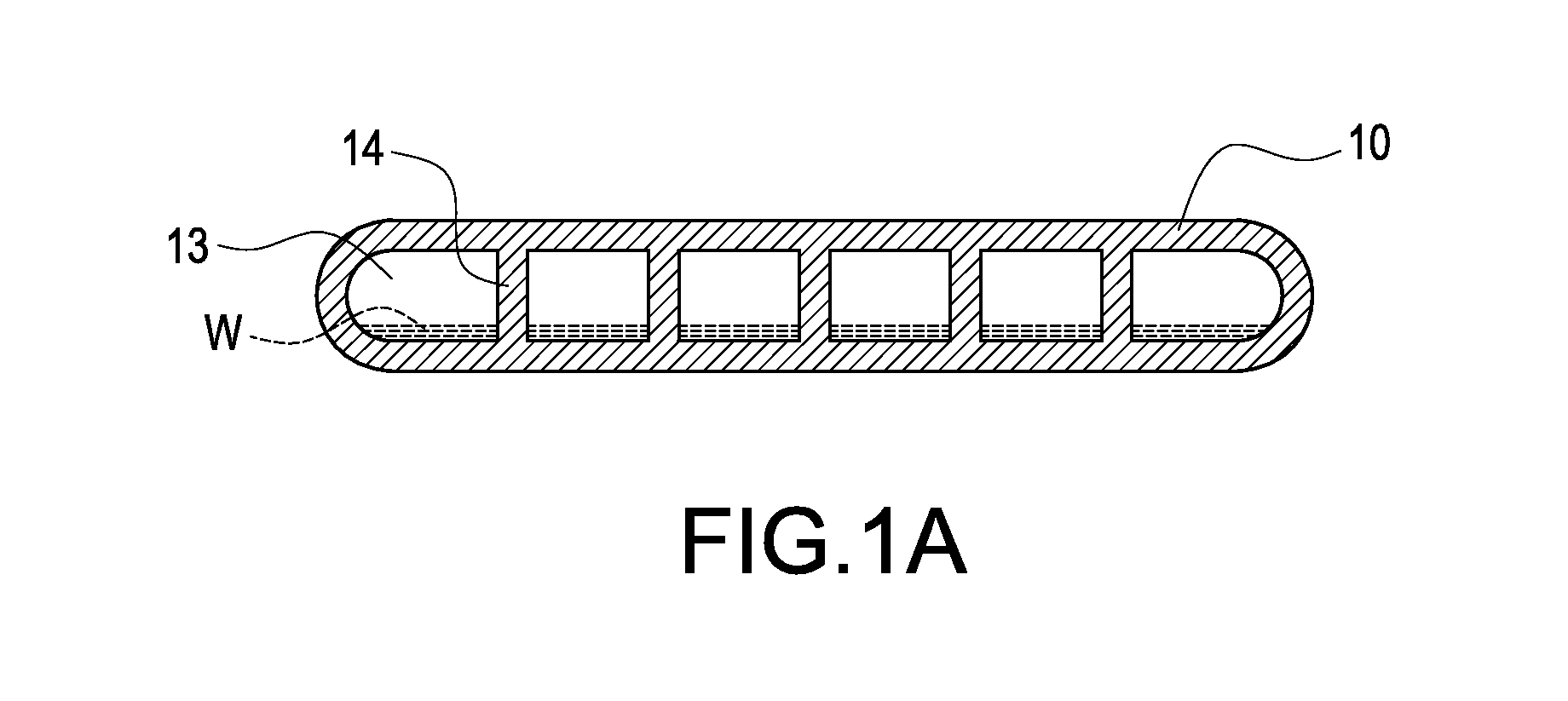
[0038]As shown in FIG. 1, the flat pipe 10 is configured to have a plurality of bending sections 11 and a plurality of connecting sections 12 each connecting adjacent two bending sections 11. As shown in FIG. 1A, the interior of the flat pipe 10 is filled with a working fluid W and provided with a plurality of channels 13 separated from each other for allowing the working fluid W to flow through. More specifically, the flat pipe 10 is made of metallic material of ...


PUM


Abstract

The present invention relates to a multi-channel flat-tube serpentine heat exchanger and a heat exchange apparatus. The heat exchanger includes a flat pipe, a fin set and a divider assembly. The flat pipe has bending sections and connecting sections. The flat pipe is filled with a working fluid and has channels. The fin set is connected between the connecting sections to increase heat-exchange area of the flat pipe. The divider assembly is connected to the flat pipe to divide the flat pipe into a heat-absorbing region and a heat-releasing region. The working fluid in the heat-absorbing region absorbs heat to evaporate and then flows into the heat-releasing region along the channels. The evaporated working fluid condenses in the heat-releasing region to flow back to the heat-absorbing region along the channels by means of gravity. Therefore, the present invention has a reduced production cost and an increased heat-exchange efficiency.

Description

BACKGROUND OF THE INVENTION[0001]1. Field of the Invention[0002]The present invention relates to a heat exchanger and a heat exchange apparatus, and in particular to a multi-channel flat-tube serpentine heat exchanger and heat exchange apparatus.[0003]2. Description of Prior Art[0004]The conventional air-to-air heat exchanger is manufactured by the following steps of: (1) providing a plurality of copper pipes and a fin set constituted of fins; (2) drilling through holes on each fin for allowing the respective copper pipes to pass through; (3) disposing the copper pipes through the through holes to connect the fins together; (4) soldering the gaps between the copper pipes and the through holes to fix the copper pipes to the fin set; and (5) soldering two adjacent copper pipes penetrating the fin set by a copper curved pipe, thereby forming a continuous zigzag heat exchanger.[0005]However, the conventional heat exchanger has the following problems. The gaps between the copper pipes an...

Claims


Application Information

Patent Timeline
Patent Type & Authority Applications(United States)
IPC IPC(8): F28F1/12
CPCF28D15/0275F28F1/12F28F9/0131F28D15/0266F28D15/0233F28D2021/0028F28F2009/226F28D1/0478
Inventor LANGE, TORBEN BJERRISGAARDWANG, I-CHINGLIN, JHIH-YE
Owner COOLING HOUSE
Why Eureka
Try Eureka