Method tubular element of a fall pipe, fall pipe assembled from such elements, coupling between two such tubular elements and method for assembling the fall pipe

Active Publication Date: 2012-10-25
DEME OFFSHORE NL BV
View PDF5 Cites 4 Cited by
  • Summary
  • Abstract
  • Description
  • Claims
  • Application Information

AI Technical Summary

Benefits of technology

[0029]Although a fall pipe can be assembled of any desired length using the element according to the invention, the element is particularly suitable for assembling a fall pipe with a length of more than 1000 metres

Problems solved by technology

Elements of the fall pipe may displace, in particular rotate, relative to each other due to for instance the depositing of material, currents and movements of the vessel or possible contact of the fall pipe with the bottom, whereby there can occur the risk of uncoupling of adjoining elements.
This reduces the risk of adjoining se

Method used


Image

  • Method tubular element of a fall pipe, fall pipe assembled from such elements, coupling between two such tubular elements and method for assembling the fall pipe
  • Method tubular element of a fall pipe, fall pipe assembled from such elements, coupling between two such tubular elements and method for assembling the fall pipe
  • Method tubular element of a fall pipe, fall pipe assembled from such elements, coupling between two such tubular elements and method for assembling the fall pipe

Examples


Example

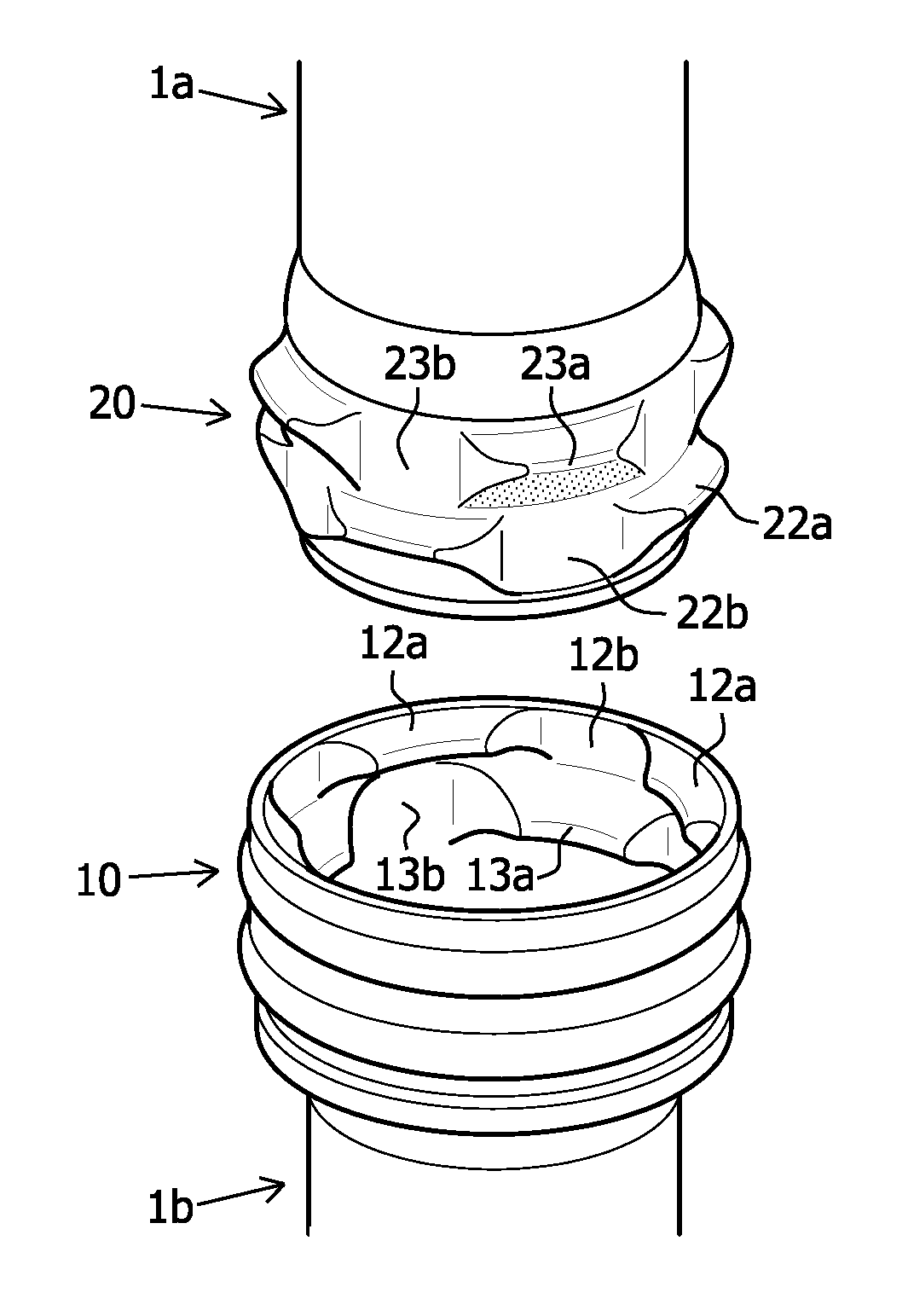
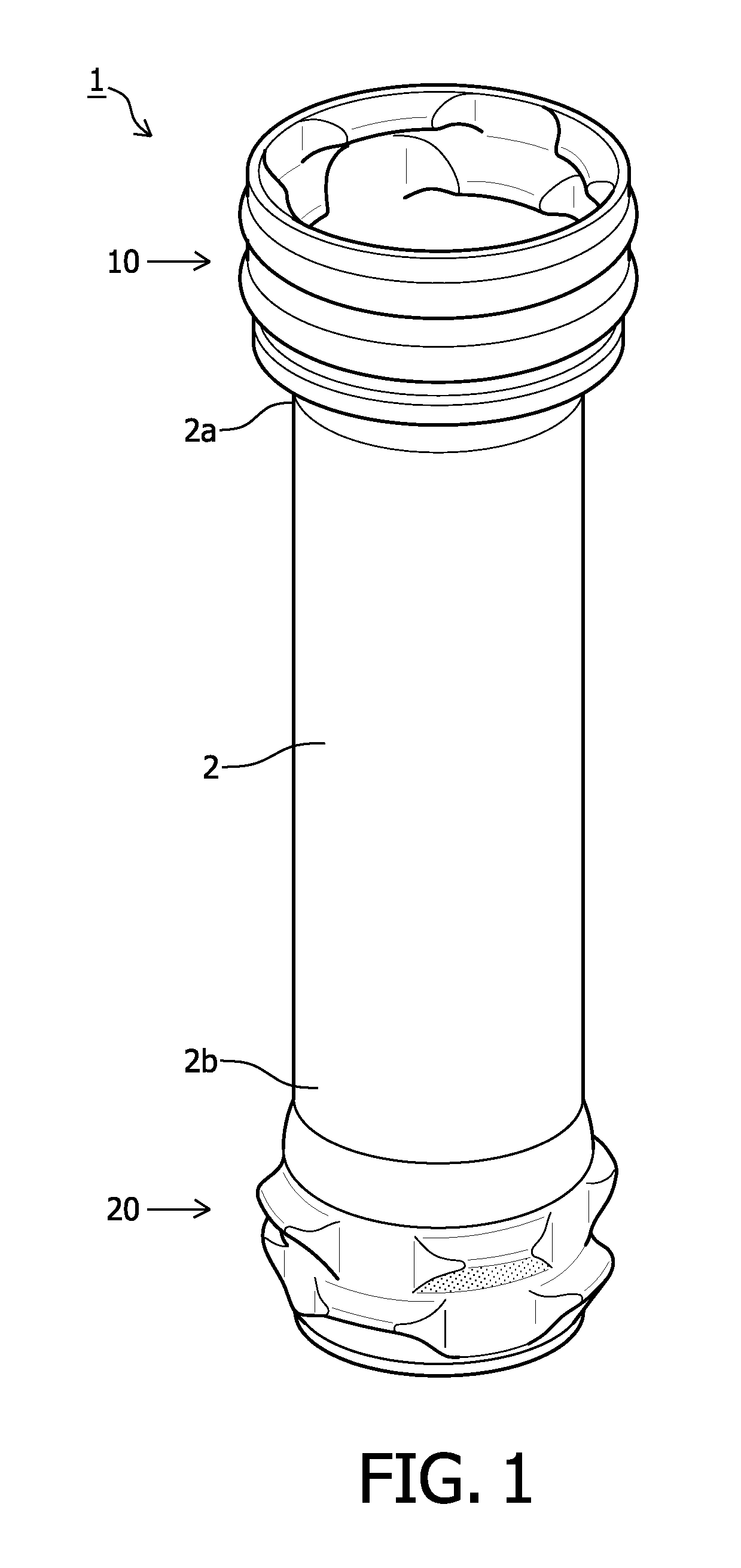
[0039]Referring to FIG. 1, a tubular element 1 according to the invention is shown. Tubular element 1 comprises tubular part 2 having at a first outer end 2a of tubular part 2 a female coupling part 10 and at a second outer end 2b of tubular part 2 a male coupling part 20. Both tubular part 2 and coupling parts (10, 20) are manufactured from an aluminium alloy. Coupling parts (10, 20) are connected concentrically to tubular part 2 by means of friction welds.

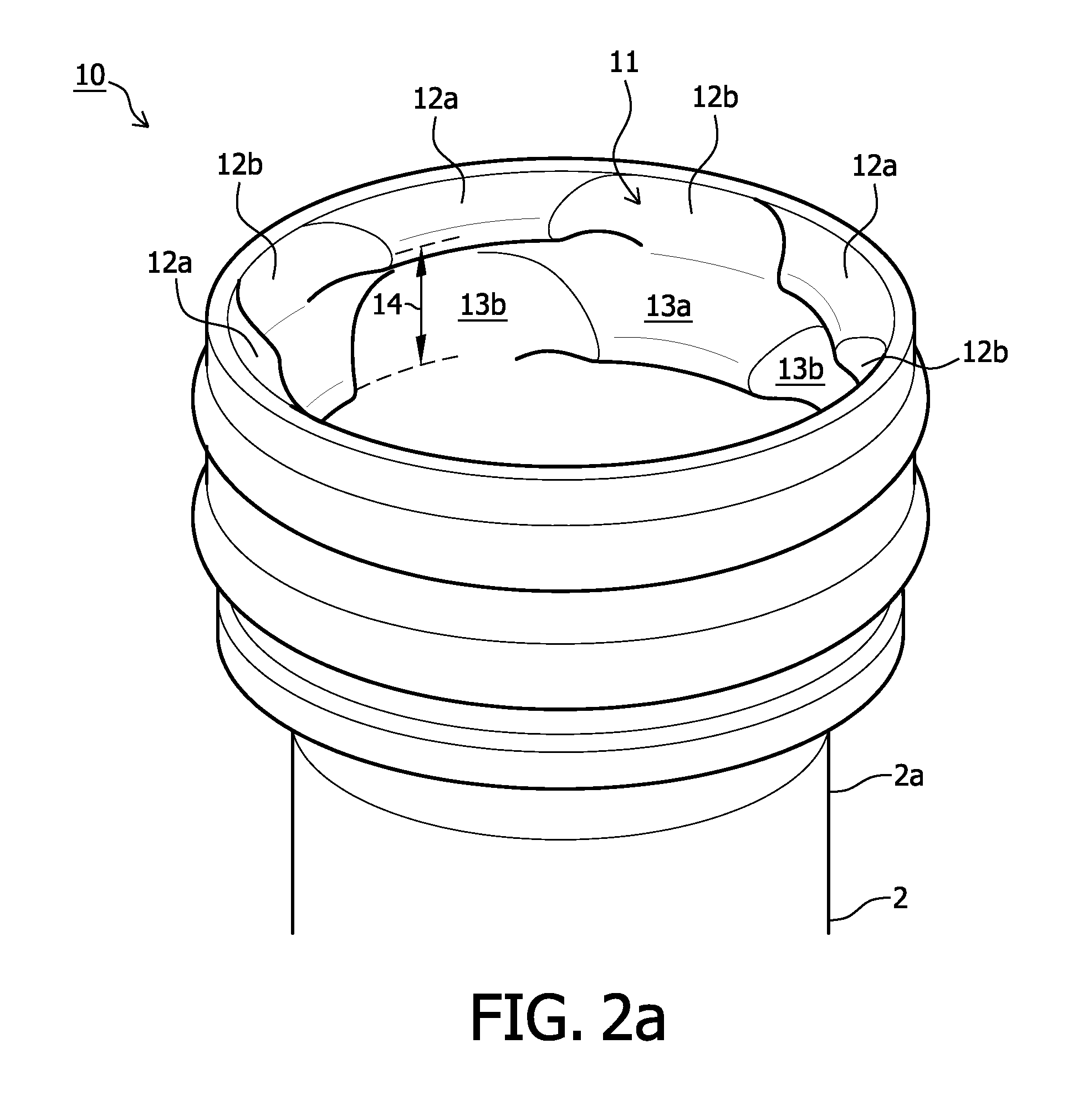
[0040]Referring to FIG. 2a, a female coupling part 10 is shown of the tubular element 1 shown in FIG. 1. Female coupling part 10 is provided on an inner periphery 11 with two annular flanges (12, 13) lying at a mutual axial distance 14. Annular flanges (12, 13) are divided in the peripheral direction of annular coupling part 10 into inward protruding segments (12a, 13a) which leave recesses (12b, 13b) clear therebetween. Segments 12a of upper annular flange 12 are arranged offset relative to segments 13a of lower annular flange 1...


PUM

PropertyMeasurementUnit
Fractionaaaaaaaaaa
Fractionaaaaaaaaaa
Fractionaaaaaaaaaa

Abstract

The invention relates to a tubular element of a fall pipe used for the purpose of depositing materials underwater from a fall pipe vessel. The fall pipe element comprises a male and a female coupling part for coupling to another element of the same form. The coupling parts are provided on respectively an outer periphery and inner periphery thereof with an annular flange which is divided in peripheral direction into segments which leave recesses clear therebetween. For coupling purposes segments of a male coupling part are placed through recesses of a female coupling part and slid by rotation under segments of the female coupling part. The invention likewise relates to a fall pipe and a method for assembly thereof. The fall pipe is particularly suitable for depositing material at great water depth.

Description

CROSS-REFERENCE TO RELATED APPLICATIONS[0001]This application is a §371 national stage entry of International Application No. PCT / EP2010 / 050361 filed Jun. 11, 2010, which claims priority from NI, 2003026 filed Jun. 15, 2009, both of which are hereby incorporated by reference in their entirety, for all purposes herein.FIELD OF THE INVENTION[0002]The invention relates to a tubular element of a fall pipe used for the purpose of depositing materials, in particular rocks, on an underwater bottom. The invention also relates to a fall pipe assembled from such elements, a coupling between two such elements and to a method for assembling the fall pipe.[0003]It is known to equip ships with provisions for assembling and carrying a fall pipe for the purpose of depositing materials, in particular rocks, on an underwater bottom. High standards are set for such a fall pipe. It must for instance be possible to easily store a good fall pipe on board the ship, and to assemble and disassemble it quick...

Claims


Application Information

Patent Timeline
IPC IPC(8): F16L37/252B23P11/00B65G11/02
CPCY10T29/49826F16L37/2445
Inventor GABRIEL, JAN
Owner DEME OFFSHORE NL BV
Why Eureka
Try Eureka