Embedded permanent magnet electric motor

a permanent magnet electric motor and permanent magnet technology, applied in the direction of dynamo-electric machines, magnetic circuit rotating parts, magnetic circuit shapes/forms/construction, etc., can solve the problems of difficult winding of stators, inability to achieve high-speed rotation, and greater coil inductance, so as to facilitate the mounting of stator coils and reduce stator coil inductance , the effect of high outpu

Inactive Publication Date: 2012-10-25
MITSUBISHI ELECTRIC CORP
View PDF5 Cites 14 Cited by
  • Summary
  • Abstract
  • Description
  • Claims
  • Application Information

AI Technical Summary

Benefits of technology

[0010]The present invention aims to solve the above problems and an object of the present invention is to provide an embedded permanent magnet electric motor that facilitates mounting of a stator coil, that enables stator coil inductance to be reduced, and that also enables eddy currents that arise in permanent magnets to be reduced.
[0012]According to the present invention, because the stator core is configured so as to have open slots, mounting of the stator coil is facilitated, and stator coil inductance is also reduced, enabling high output to be achieved during high-speed rotation. Because a stator core that is configured so as to have open slots, and a rotor core that has an outer circumferential surface that is constituted by a plurality of convex surfaces in which circular arc-shaped curved surfaces are arranged continuously at a uniform angular pitch circumferentially are used, eddy currents that arise in the permanent magnets can be reduced. Thus, because eddy current loss in the permanent magnets is reduced, and temperature increases in the permanent magnets are suppressed, decreases in magnetic flux and thermal demagnetization of the permanent magnets can be prevented.

Problems solved by technology

In conventional permanent magnet synchronous electric motors, because slots of the stator core are configured into semi-closed slots that have flange portions that extend circumferentially outward from tip ends of the teeth, it is hard to wind the stator coil, and coil inductance is greater, and one problem has been that high output cannot be achieved during high-speed rotation.
However, the change in stator magnetic flux that passes through the permanent magnets per unit time is greater, and eddy currents in the permanent magnet increase, giving rise to new problems such as the temperature of the permanent magnets increasing, the magnetic flux of the permanent magnets decreasing, or thermal demagnetization occurring.

Method used


Image

  • Embedded permanent magnet electric motor
  • Embedded permanent magnet electric motor
  • Embedded permanent magnet electric motor

Examples


embodiment 1

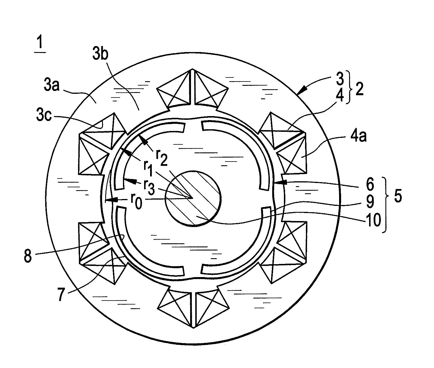
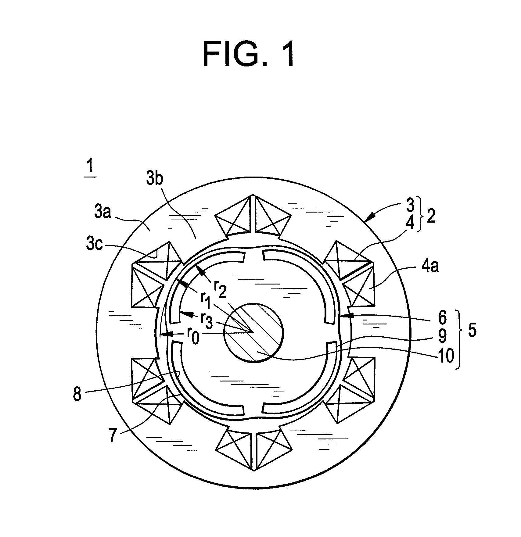
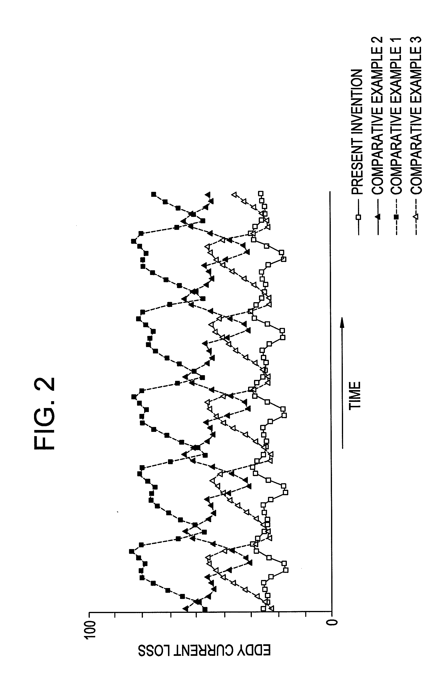
[0028]FIG. 1 is a cross section that schematically shows an overall configuration of an embedded permanent magnet electric motor according to Embodiment 1 of the present invention, FIG. 2 is a graph that shows results when eddy current loss of permanent magnets in the embedded permanent magnet electric motor according to Embodiment 1 of the present invention was analyzed, FIG. 3 is a cross section that schematically shows an overall configuration of an embedded permanent magnet electric motor according to Comparative Example 1, FIG. 4 is a cross section that schematically shows an overall configuration of an embedded permanent magnet electric motor according to Comparative Example 2, FIG. 5 is a cross section that schematically shows an overall configuration of an embedded permanent magnet electric motor according to Comparative Example 3, FIG. 6 is a diagram that explains an eddy current loss reducing mechanism in an embedded permanent magnet electric motor, and FIG. 7 is a diagram...

embodiment 2

[0053]FIG. 8 is an end elevation that schematically shows a stator core that is used in an embedded permanent magnet electric motor according to Embodiment 2 of the present invention.

[0054]In FIG. 8, a stator core 3B is formed by laminating and integrating a large number of electromagnetic steel plates that have been punched into identical shapes, for example, and has: an annular core back 3a; and six teeth 11 that are formed so as to have tapered shapes in which respective circumferential widths become gradually narrower radially inward, that are disposed so as to extend radially inward from an inner circumferential surface of the core back 3a, and that are arranged at a uniform angular pitch circumferentially.

[0055]Moreover, the rest of the configuration is formed in a similar manner to Embodiment 1 above.

[0056]According to Embodiment 2, because each of the teeth 11 are formed so as to have a tapered shape in which a circumferential width become gradually narrower radially inward,...

embodiment 3

[0057]FIG. 9 is an end elevation that schematically shows a stator core that is used in an embedded permanent magnet electric motor according to Embodiment 3 of the present invention.

[0058]In FIG. 9, core segments 12 are formed by laminating and integrating a large number of electromagnetic steel plates that have been punched into identical shapes, and have: a core back portion 13; and a tooth 3b that is disposed so as to extend radially inward from a circumferential center of an inner circumferential surface of the core back portion 13. A stator core 3C is configured by press-fitting six core segments 12 into an annular frame (not shown) so as to be arranged in an annular shape circumferentially. The core back portions 13 are linked circumferentially to configure a core back 3a.

[0059]Moreover, the rest of the configuration is formed in a similar manner to Embodiment 1 above.

[0060]According to Embodiment 3, because the stator core 3C is configured so as to be divided into six core ...


PUM


Abstract

The embedded permanent magnet electric motor includes: a rotor having: a rotor core that has an outer circumferential surface that is constituted by a plurality of convex surfaces that are circular arc-shaped curved surfaces that are arranged continuously at a uniform angular pitch circumferentially; and a plurality of permanent magnets that are embedded in the rotor core so as to be positioned on a radially inner side of each of the circular arc-shaped curved surfaces; and a stator having: a stator core in which teeth are respectively disposed so as to extend radially inward from an annular core back and are arranged at a uniform angular pitch circumferentially to configure open slots; and a stator coil that is constituted by a plurality of concentrated winding coils that are wound into concentrated windings on each of the teeth.

Description

BACKGROUND OF THE INVENTION[0001]1. Field of the Invention[0002]The present invention relates to an embedded permanent magnet electric motor that is used in an automotive motor, for example.[0003]2. Description of the Related Art[0004]Conventional permanent magnet synchronous electric motors include: a stator that has: a stator core that is configured by arranging a plurality of core segments annularly; and a stator coil that is constituted by a concentrated winding coil that is wound into concentrated windings on respective teeth of the core segments; and a rotor that is configured by fixing a plurality of permanent magnets to an outer circumferential surface of a cylindrical rotor core (see Patent Literature 1, for example).[0005]Patent Literature 1: Japanese Patent Laid-Open No. HEI 11-89197 (Gazette)[0006]In conventional permanent magnet synchronous electric motors, because slots of the stator core are configured into semi-closed slots that have flange portions that extend circu...

Claims


Application Information

Patent Timeline
Patent Type & Authority Applications(United States)
IPC IPC(8): H02K1/27
CPCH02K1/148H02K2201/03H02K21/16H02K1/276
Inventor NISHIMURA, SHINJIKURODA, YOICHIINOUE, MASAYAHAZEYAMA, MORIYUKI
Owner MITSUBISHI ELECTRIC CORP
Why Eureka
Try Eureka