Eureka AIR delivers breakthrough ideas for toughest innovation challenges, trusted by R&D personnel around the world.

Current sensor with a magnetic core

Inactive Publication Date: 2012-10-25
ABB (SCHWEIZ) AG
View PDF28 Cites 6 Cited by
  • Summary
  • Abstract
  • Description
  • Claims
  • Application Information

AI Technical Summary

Benefits of technology

[0040]In this embodiment, too, the core may have a mainly circular, ovaloid or rectangular shape, and may be made from stacked core sheets or from a few layers of thin strip-wound magnetic tape, which form a ring enclosing the primary conductor. The core may overlap in a plane region of the core, where it forms an air gap that fully encloses the flux sensor element. The core may have curved parts or local bends to generate the specified overlap. It can be fixed by resin impregnation, spot welding, moulding, plastic encapsulation, or other suitable means. The cross section of the overlap can be larger than the core cross section.
[0046]The sensor element can be better protected from external magnetic interference.
[0049]The air gap can be oriented along directions where interfering fields are smaller.
[0027]According to a further exemplary embodiment, the first and second overlap regions form first and second gaps, and the first gap is configured as air-gap to contain the sensor element, and the second gap is filled with a soft magnetic spacer means for magnetically short-circuiting the second gap. So, one of the overlaps forms a narrow gap, which contains the sensor element. The other overlap makes good magnetic contact between the two surfaces without intentional formation of an air gap.

Problems solved by technology

However, in multi-phase systems with other conductors and currents there may be an impact on the sensor accuracy from magnetic cross talk.
This can be mainly due to the effect of the air-gap, which causes magnetic stray fields from the core induction and at the same time a vulnerability of the current sensor to external magnetic fields.
With known state-of-the art current sensor designs a reduction of the magnetic reluctance is limited in cases when the core has a small core cross section, as the length of the air-gap cannot be reduced below the minimum thickness of the flux sensor element, and the sensor has a certain minimum lateral dimension, such that the flux sensor element may be insufficiently shielded by the core or even protruding from the air gap and thus be exposed to the influence of external stray fields.

Method used


Image

  • Current sensor with a magnetic core
  • Current sensor with a magnetic core
  • Current sensor with a magnetic core

Examples


Embodiment Construction

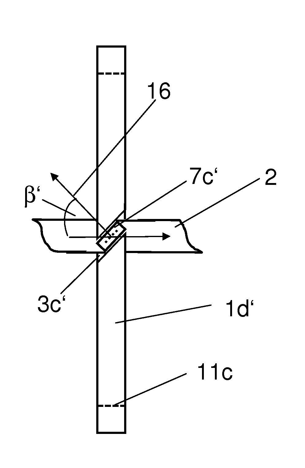
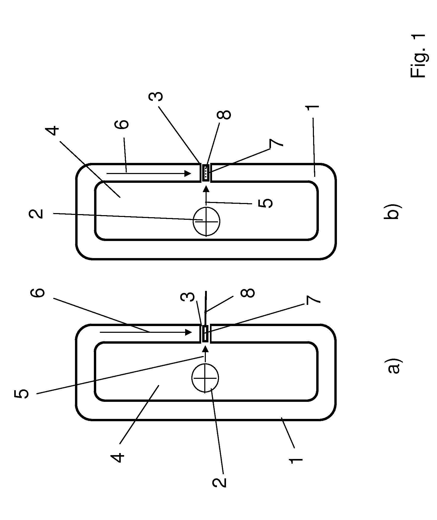
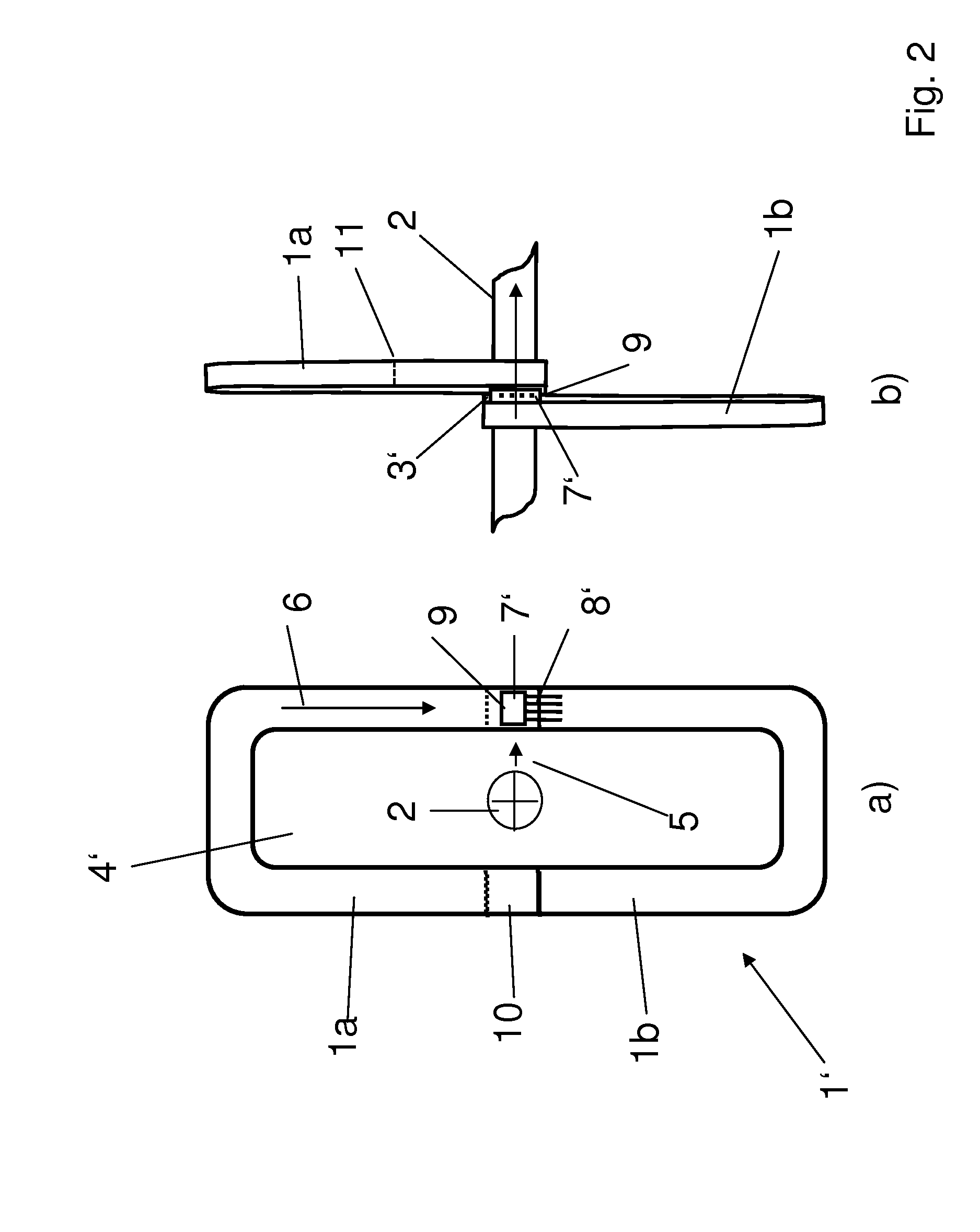
[0019]An exemplary current sensor is disclosed with a reduction of the magnetic cross-talk sensitivity, both in an open and in a closed loop configuration, notwithstanding a potentially limited cross-sectional area of the core.

[0020]In an exemplary embodiment, a cross-sectional area of an air-gap is larger than a cross-sectional area of a core.

[0021]As referenced herein, the cross-sectional area of the air-gap refers, for example, to an area of the cross-section perpendicularly to the direction of the air-gap, whereby the direction of the air-gap is defined as the main direction of the magnetic field in the air-gap. Cross-sectional area of the core refers, for example, to an area of the cross-section of the core perpendicularly to the circumferential direction of the core.

[0022]An exemplary advantageous effect of a current sensor design as disclosed herein is that the magnetic reluctance of the air-gap is reduced as far as possible, without a need to significantly increase the cross...


PUM


Abstract

A current sensor is disclosed, with a ring-shaped magnetic core, the core enclosing the primary conductor with the current to be measured, the core having an air-gap containing a sensor element for measuring the magnetic core induction, whereby the cross-sectional area of the air-gap is larger than the cross-sectional area of the core.

Description

RELATED APPLICATION[0001]This application claims priority under 35 U.S.C. §119 to European Patent Application No. 11003399.0 filed in Europe on Apr. 21, 2011, the entire content of which is hereby incorporated by reference in its entirety.FIELD[0002]The present disclosure relates to a current sensor with a ring-shaped magnetic core, such as a core enclosing a primary conductor carrying current to be measured, the core having an air-gap containing a sensor element for measuring magnetic core induction.BACKGROUND INFORMATION[0003]Current sensors of two types, open and closed loop, are able to measure both AC and DC currents. These sensors can feature a soft magnetic, ring-shaped, core, which encloses a primary conductor with current that shall be measured. The core can be composed of either a strip-wound metal tape, stacked magnetic sheet steel or bulk ferrite. The core can have an air gap, which is aligned along the circumferential direction of the core. FIG. 1 shows a known configur...

Claims


Application Information

Patent Timeline
IPC IPC(8): G01R33/04
CPCG01R15/207G01R15/183
Inventor DISSELNKOTTER, ROLFHOZOI, ADRIAN
Owner ABB (SCHWEIZ) AG
Why Eureka
Eureka Blog
Learn More