Light irradiation apparatus, pseudo-sunlight irradiation apparatus and solar panel inspection apparatus

a technology of light irradiation and solar panel, which is applied in the direction of fixed installation, lighting and heating equipment, instruments, etc., can solve the problem that the peripheral part of the halogen lamp cannot be covered, and achieve the effect of preventing the decrement of directivity performance and reducing the degree of spectrum correspondence with sunligh

Inactive Publication Date: 2012-10-25
SHARP KK
View PDF5 Cites 44 Cited by
  • Summary
  • Abstract
  • Description
  • Claims
  • Application Information

AI Technical Summary

Benefits of technology

[0026]According to the present invention with the structure described above, a light shielding member is placed in between adjacent first light guiding members and / or adjacent second light guiding members, so that degradation of directivity performance due to stray light with poor directivity, entering and propagating through the tapered light guiding members, can be prevented, and thus the decrease in the degree of spectrum correspondence with sunlight can be prevented.

Problems solved by technology

Thus, in a case of a halogen lamp, since the temperature gets high, the periphery of the halogen lamp cannot be covered.

Method used


Image

  • Light irradiation apparatus, pseudo-sunlight irradiation apparatus and solar panel inspection apparatus
  • Light irradiation apparatus, pseudo-sunlight irradiation apparatus and solar panel inspection apparatus
  • Light irradiation apparatus, pseudo-sunlight irradiation apparatus and solar panel inspection apparatus

Examples


embodiment 1

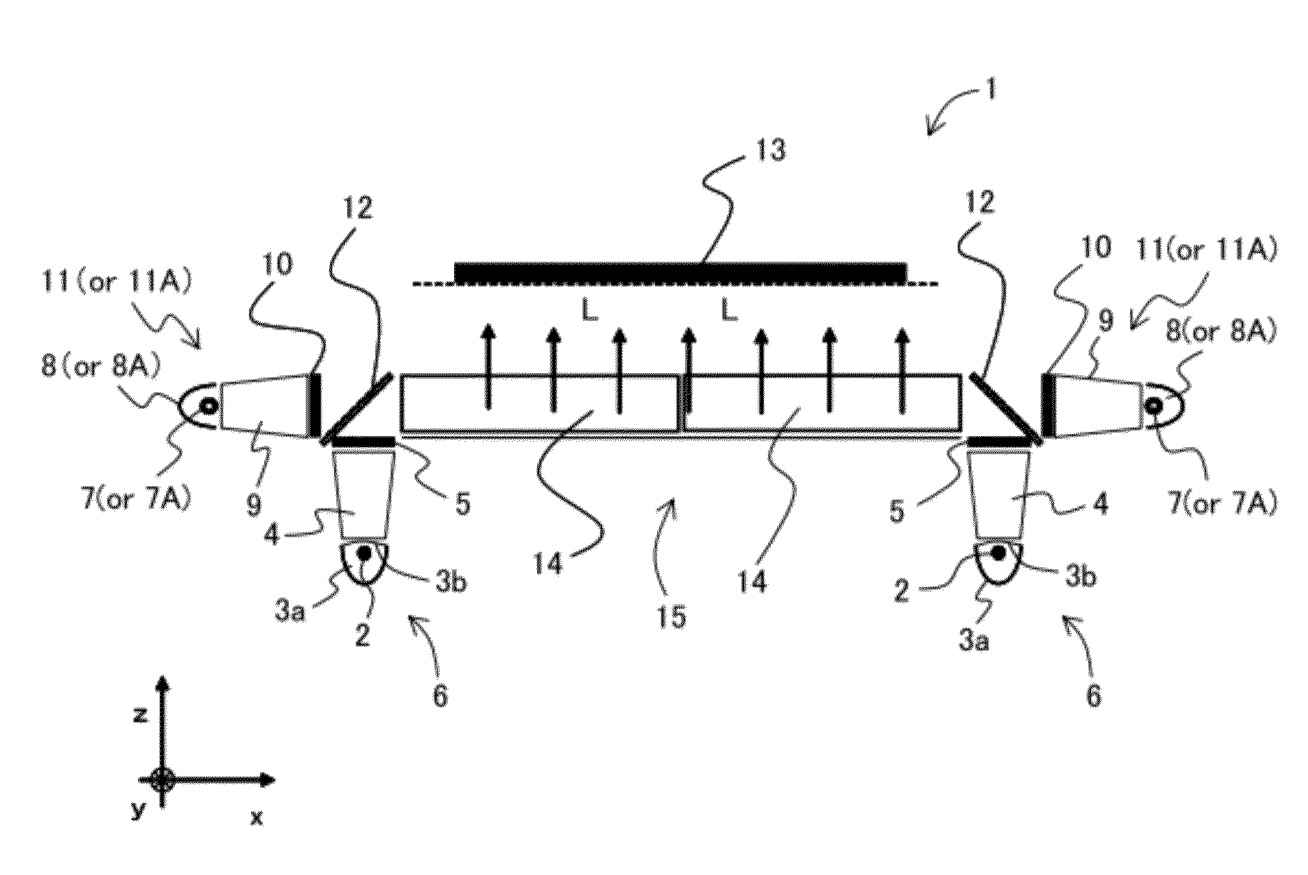
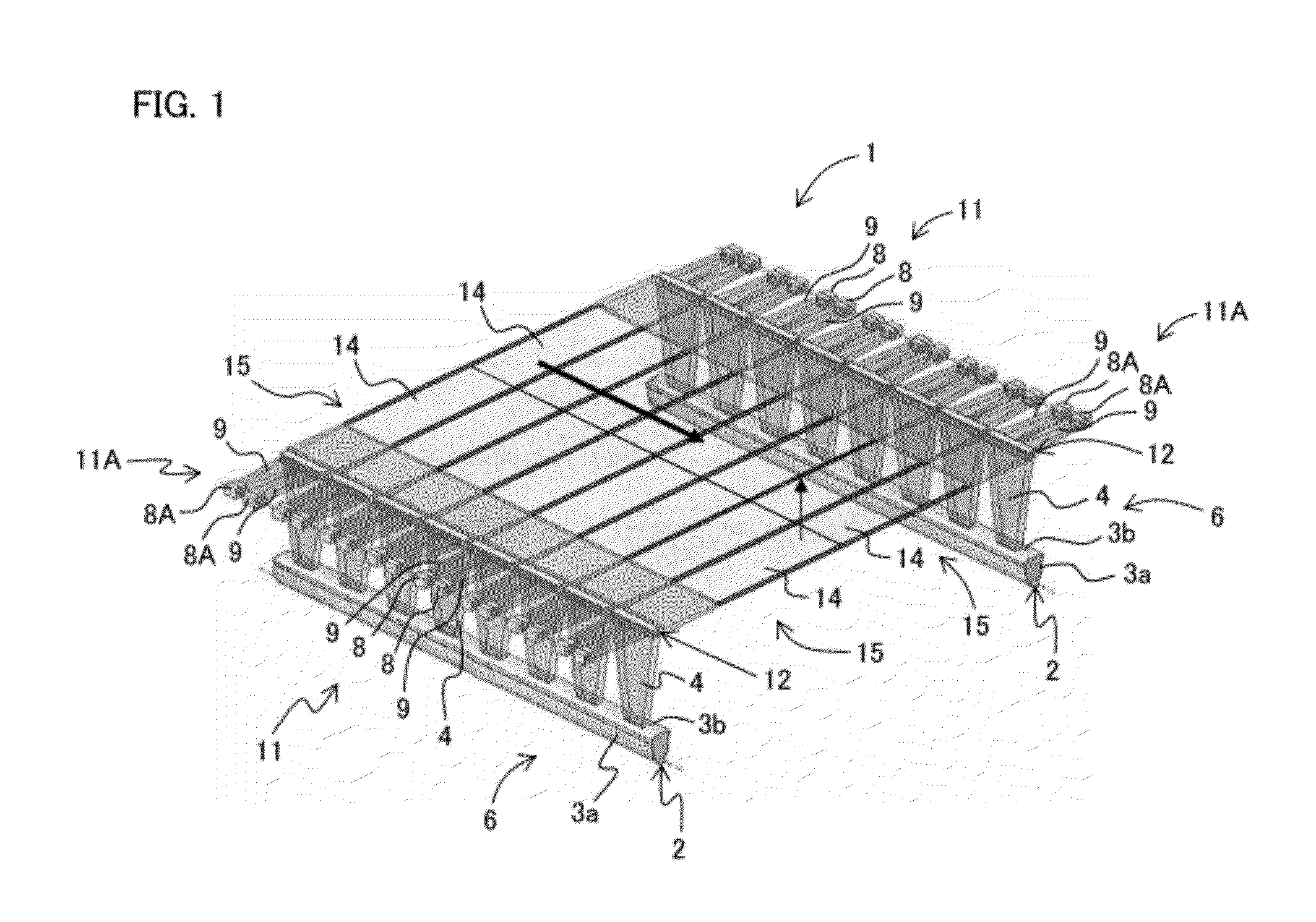
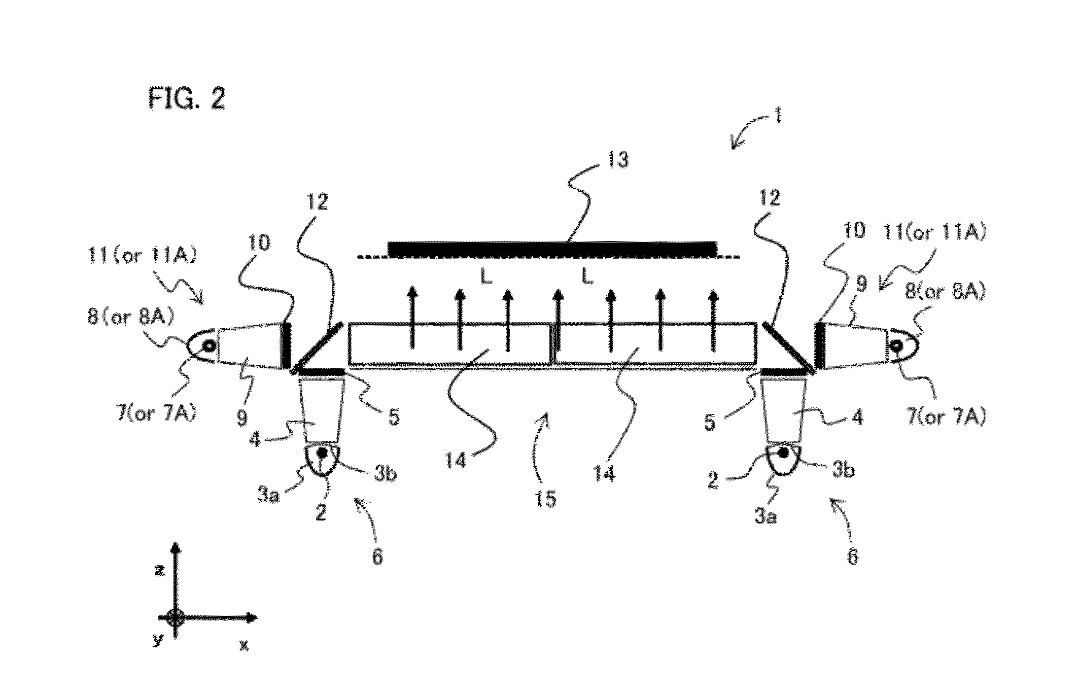
[0068]FIG. 1 is a perspective view schematically illustrating a structural example of an important part of a pseudo-sunlight irradiation apparatus according to Embodiment 1 of the present invention. FIG. 2 is a longitudinal cross sectional view schematically illustrating a structural example of an important part of the pseudo-sunlight irradiation apparatus in FIG. 1.

[0069]In FIGS. 1 and 2, a pseudo-sunlight irradiation apparatus 1 according to Embodiment 1 is equipped with a first light irradiation apparatus 6. The first light irradiation apparatus 6 comprises: a xenon light source 2 of a xenon lamp; a reflector 3a for housing the xenon light source 2 therein, with an inner surface functioning as a reflection surface; an aperture plate 3b for covering a front portion of the reflector 3a; a tapered light guiding member 4 functioning as a tapered coupler for taking a xenon output light into a bottom end surface thereof and propagating the light through the inside to improve the direct...

embodiment 2

[0103]In Embodiment 1, the case has been described where the third light irradiation apparatuses 15 are placed on the left and right sides, and light guiding members 14 are in contact with each other at their end surfaces. In Embodiment 2, a case will be described where light guiding members 14 on the left and right sides are integrated with each other so that the third light irradiation apparatuses 15 on the left and right sides in Embodiment 1 are also integrated with each other.

[0104]Specifically, in Embodiment 1, the case has been described where, as the pseudo-sunlight irradiation apparatus 1, a first light irradiation apparatus 6, a second light irradiation apparatus 11, and a third light irradiation apparatus 15 are unitized as a set; the unitized sets are placed facing each other in the left and right direction; and a plurality of two such units, in which the other end surfaces of the respective third light guiding members 14 and 14 of the third light irradiation apparatus 1...


PUM


Abstract

The degradation of directivity performance due to stray light with poor directivity entering and propagating through tapered light guiding members can be prevented, and thus the decrease in the degree of spectrum correspondence with sunlight can be prevented. A light shielding member 41 is placed in between adjacent tapered light guiding members 4. Specifically, the light shielding member 41 is attached to or coiled around the surface of a circumference wall of the tapered light guiding member 4, other than one end surface and the other end surface for allowing light to enter and exit. Further, the light shielding member 41 is placed so that stray light will not enter the tapered light guiding member 4 from the circumferential wall thereof, other than the one end surface and the other end surface.

Description

TECHNICAL FIELD[0001]The present invention relates to a light irradiation apparatus for emitting light with high directivity to a subject to be irradiated, a pseudo-sunlight irradiation apparatus for emitting pseudo-sunlight onto the subject to be irradiated using the light irradiation apparatus, and a solar panel inspection apparatus for measuring an output characteristic of a solar panel to determine quality, using the pseudo-sunlight irradiation apparatus.BACKGROUND ART[0002]In a conventional pseudo-sunlight irradiation apparatus for use as a light source apparatus for reproducing the spectral distribution of sunlight with high precision, an attempt has been conventionally made to unify the illuminance distribution on a measurement subject by lighting a xenon lamp to let pseudo-sunlight passing through an optical filter (air mass filter) undergo diffuse reflection with a reflection plate to obtain light having a desired spectrum.[0003]Output light from a lamp light source is allo...

Claims


Application Information

Patent Timeline
IPC IPC(8): F21V9/02F21V13/12F21V13/02
CPCG01N17/004G02B6/0026G02B6/0028G02B6/0068G02B6/0078F21S8/006
Inventor MINAMI, KOHJITADANO, HIROYUKI
Owner SHARP KK
Why Eureka
Try Eureka