Cleaning method and film depositing method

Inactive Publication Date: 2012-10-25
TOKYO ELECTRON LTD
View PDF2 Cites 54 Cited by
  • Summary
  • Abstract
  • Description
  • Claims
  • Application Information

AI Technical Summary

Benefits of technology

[0012]In view of the above, an embodiment of the present invention provides a cleaning method and a film depositing method

Problems solved by technology

However, the cleaning step (i.e. removing polyimide adhered to the film deposition chamber by which a polyimide film is deposited) has the following problems.
Thus, the yield of the film deposition apparatus decreases.
Further, even in a

Method used


Image

  • Cleaning method and film depositing method
  • Cleaning method and film depositing method
  • Cleaning method and film depositing method

Examples


first embodiment

[0032]First, a description is given, with reference to FIG. 1 through FIG. 10, of a cleaning method and a film depositing method according to the first embodiment of the present invention.

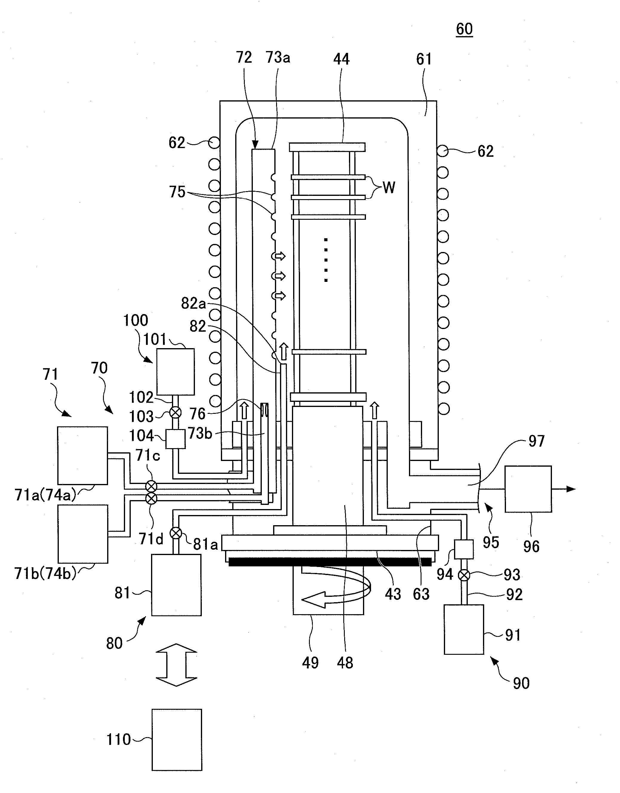
[0033]The film depositing method according to this embodiment may be applied to a film deposition apparatus configured to deposit a polyimide film on a substrate held in a film deposition chamber by feeding the substrate with a first raw material gas, which is, for example, vaporized pyromellitic dianhydride (hereinafter abbreviated as “PMDA”), and a second raw material gas, which is, for example, vaporized 4,4′-3 oxydianiline (hereinafter, abbreviated as “ODA”).

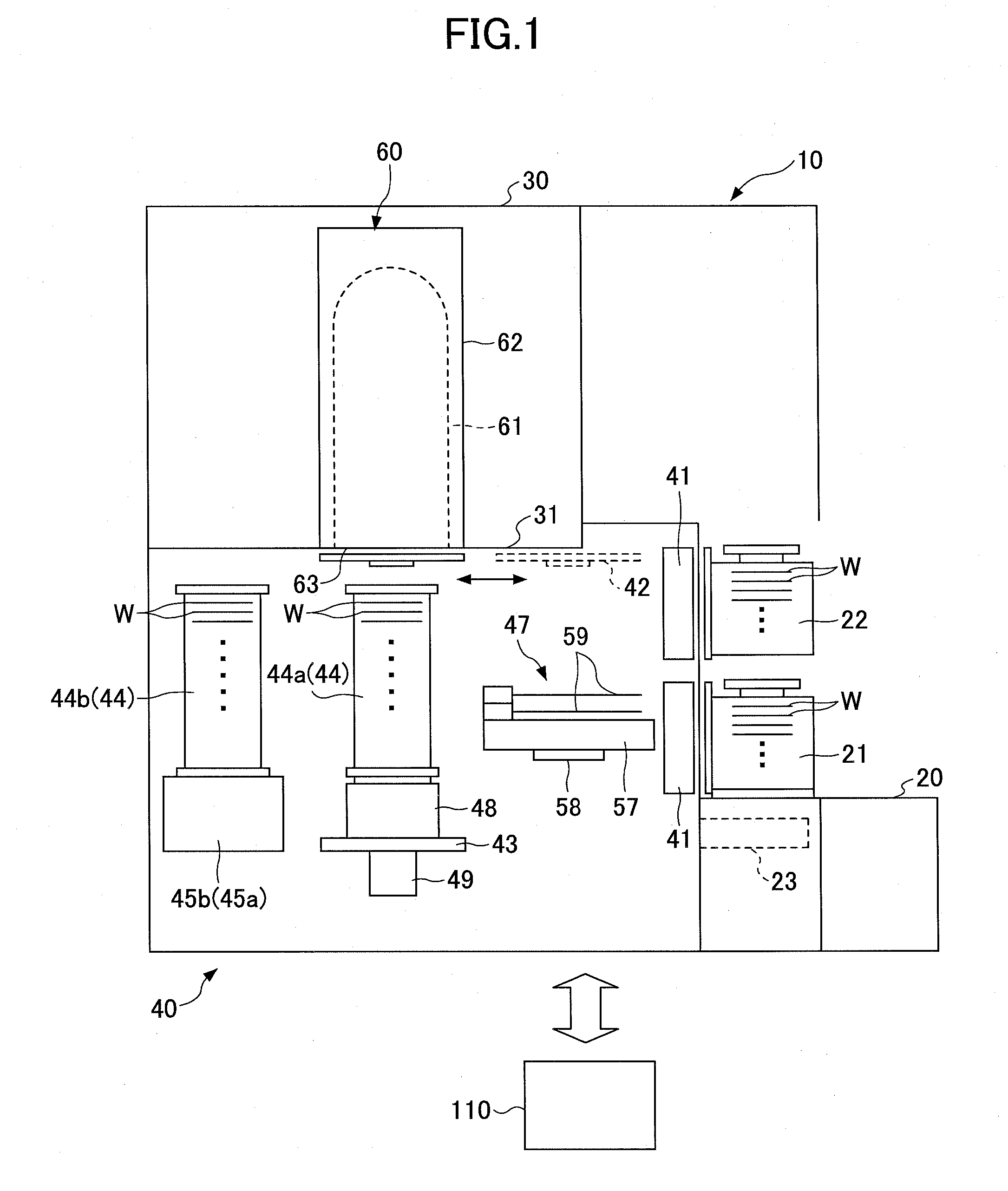
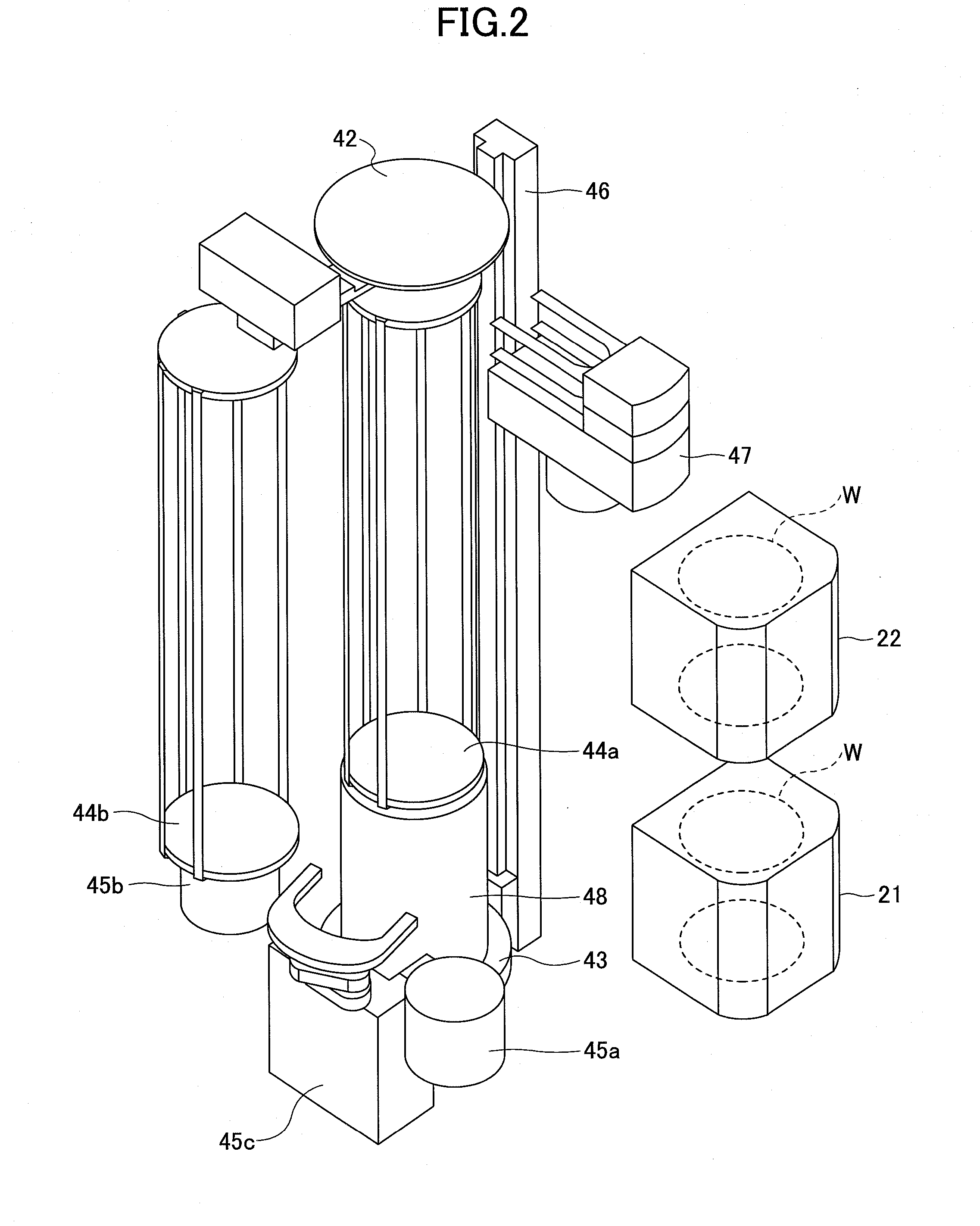
[0034]FIG. 1 is a schematic longitudinal cross-sectional view illustrating a film deposition apparatus 10 for performing the cleaning method and the film depositing method according to this embodiment. FIG. 2 is a schematic perspective view of a loading area 40. FIG. 3 is a perspective view illustrating an example of a boat 44.

[0035]The fil...

second embodiment

[0121]Next, a cleaning method and a film depositing method according a second embodiment of the present invention are described with reference to FIGS. 11-13.

[0122]As described below, unlike the cleaning method and the film depositing method of the first embodiment, the film deposition apparatus of the second embodiment includes a deposition container configured to perform single wafer processing and has a process chamber (for performing surface treatment) provided separately from the film deposition chamber.

[0123]FIG. 11 is a plan view illustrating a film deposition apparatus 120 for performing the cleaning method and the film depositing method according to the second embodiment of the present invention. FIG. 12 is a front view illustrating the configurations of a process container 130, the adhesion accelerating agent feed mechanism 80, and an exhaust mechanism 95a according to the second embodiment of the present invention. FIG. 13 is a plan view illustrating the configurations of...


PUM

PropertyMeasurementUnit
Temperatureaaaaaaaaaa
Partial pressureaaaaaaaaaa

Abstract

A cleaning method for a film deposition apparatus that deposits a polyimide film conveyed into a film deposition chamber by feeding a first source gas formed of dianhydride and a second source gas formed of diamine into the film deposition chamber, the method including the steps of: generating an oxygen atmosphere in the film deposition chamber, and removing polyimide remaining in the film deposition chamber by heating the film deposition chamber at a temperature of 360° C. to 540° C. in the oxygen atmosphere and oxidizing the polyimide.

Description

CROSS-REFERENCE TO RELATED APPLICATION[0001]The present application is based upon and claims the benefit of priority of Japanese Patent Application No. 2011-073192, filed on Mar. 29, 2011, the entire contents of which are incorporated herein by reference.BACKGROUND OF THE INVENTION[0002]1. Field of the Invention[0003]The present invention relates to a cleaning method for a film deposition apparatus for depositing a film on a substrate and a film depositing method for depositing the film on the substrate.[0004]2. Description of the Related Art[0005]In recent years, a wide range of materials from inorganic materials to organic materials are used for a semiconductor device. The characteristics of the organic materials (which inorganic materials do not have) help to optimize the properties of the semiconductor device and the manufacturing process of the semiconductor device.[0006]One of the organic materials is polyimide. Polyimide has a high insulating property. Therefore, a polyimide ...

Claims


Application Information

Patent Timeline
IPC IPC(8): C23C16/455B08B7/04B08B9/08
CPCC23C16/02C23C16/22H01L21/02304H01L21/02118H01L21/02271C23C16/4405H01L21/02H01L21/20
Inventor IDO, YASUYUKISUGITA, KIPPEIYAMAGUCHI, TATSUYA
Owner TOKYO ELECTRON LTD
Why Eureka
Try Eureka