Method and apparatus for recognizing shape of road for vehicles

a technology for recognizing the shape of roads and vehicles, applied in the direction of vehicle position/course/altitude control, process and machine control, instruments, etc., can solve the problems of affecting the correct road shape recognition, the state of turn of the vehicle is usually not in conformity with the shape, and the technique is unlikely to provide a correct estimation when the vehicle is driving, etc., to achieve the effect of calculating the shape of the road more accurately and good frequency

Active Publication Date: 2012-10-25
DENSO CORP
View PDF2 Cites 80 Cited by
  • Summary
  • Abstract
  • Description
  • Claims
  • Application Information

AI Technical Summary

Benefits of technology

[0017]Thus it is desired to provide a road shape recognition method and an apparatus for vehicles, which is able to calculate the shape of a road more correctly and with good frequency.

Problems solved by technology

However, the state of turn of the vehicle is usually not in conformity with the shape of the road on which an actual object to be controlled travels.
Therefore, the technique is unlikely to provide a correct estimation when the vehicle does not travel along the shape of the road, such as when the vehicle travels through an interchange, a ramp, i.e. on-ramp or off-ramp, a climbing lane or the like, or when the vehicle, such as a bus, is going to stop at a bus stop on an expressway.
Thus, even when the shape of the road is recognized correctly on the vehicle side, the correction of the curvature radius R is likely to impair correct road shape recognition in a situation as shown in FIG. 11.
The conventional art mentioned above may encounter a problem that roadside objects are not detected due to the presence of a preceding vehicle or that the absolute number of roadside objects is small.
Accordingly, a road edge is not calculated more correctly and with good frequency, and thus the shape of the road is unlikely to be recognized more correctly.
Further, according to the conventional art mentioned above, stationary objects that are not roadside objects may be targeted for grouping, or a base point of the grouping may be incorrect.
Thus, grouping of roadside object groups is unlikely to be performed with good accuracy.
As a result, a road edge is not calculated more correctly and with good frequency, and thus the shape of the road is unlikely to be recognized more correctly.
However, according to the conventional art mentioned above, the base point for grouping roadside objects may sometimes be incorrect, and thus grouping of roadside object groups is unlikely to be performed with good accuracy.
As a result, a road edge is not calculated more correctly and with good frequency, and thus the shape of the road is unlikely to be recognized more correctly.
Further, the conventional art mentioned above may encounter a problem that roadside objects are not detected due to the presence of a preceding vehicle or that the absolute number of roadside objects is small.
Accordingly, a road edge is not calculated more correctly and with good frequency, and thus the shape of the road is unlikely to be recognized more correctly.
In addition, the shape of the road on which an actual object to be controlled travels is unlikely to be in conformity with the state of turn of the vehicle.
However, for example, it is sometimes difficult to detect stationary objects due to the presence of a preceding vehicle, or the absolute number of stationary objects may be small.
For this reason, stationary objects do not necessarily contribute to accurately calculating a curve radius, and thus the shape of the road is not necessarily calculated correctly and with good frequency.

Method used


Image

  • Method and apparatus for recognizing shape of road for vehicles
  • Method and apparatus for recognizing shape of road for vehicles
  • Method and apparatus for recognizing shape of road for vehicles

Examples


first embodiment

[0100]Referring to FIGS. 1 to 10, a road shape recognition method and apparatus for vehicles according to a first embodiment of the present invention is described.

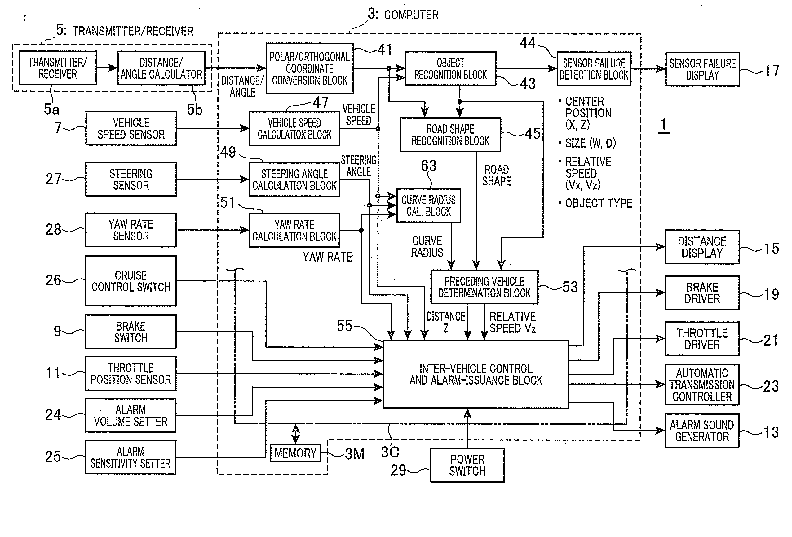
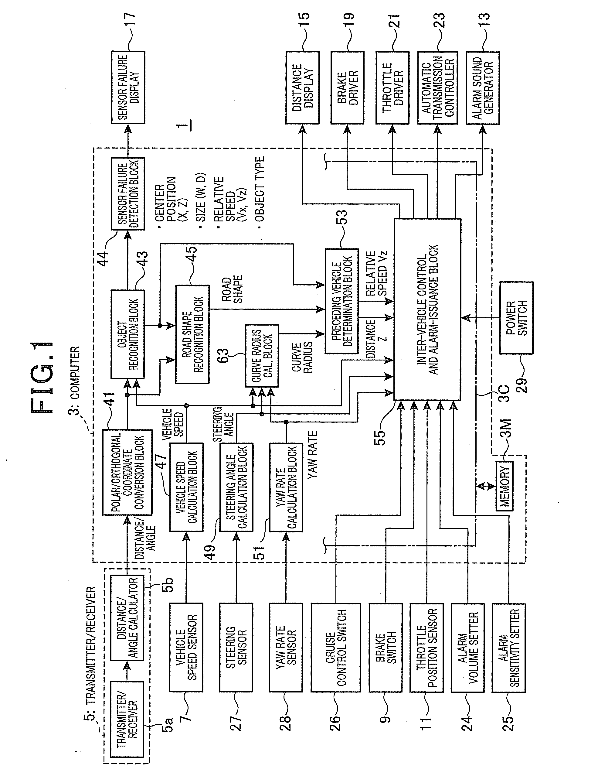
[0101]FIG. 1 illustrates a configuration of a vehicle control apparatus 1 to which the road shape recognition apparatus for vehicles is applied. The control apparatus 1 is installed in a motor vehicle and raises an alarm when obstacles are present in a predetermined situation in an area that requires issuance of an alarm or controls the vehicle speed in conformity with a preceding vehicle.

[0102]FIG. 1 is a system block diagram of the apparatus 1. The vehicle control apparatus 1 is mainly composed of a computer 3. The computer 3 is mainly composed of a microcomputer and includes an input / output interface (I / O) and various drive circuits and detection circuits. Since these hardware components are generally used ones, detailed description is omitted. Thus, the computer 3 includes a CPU (central processing unit) 3C as an arith...

second embodiment

[0273]Referring now to FIGS. 12 to 17, hereinafter is described a road shape recognition method and apparatus for vehicles according to a second embodiment of the present invention.

[0274]It should be appreciated that, in the second and the subsequent embodiments, the components identical with or similar to those in the already described embodiment are given the same reference numerals for the sake of omitting or simplifying explanation. However, in describing a process of recognizing a road shape, excessive omission of overlapped explanation may make the understanding of the context difficult. In such a case, therefore, an overlapped explanation may be given.

[0275]FIG. 12 is a diagram illustrating a configuration of a vehicle control apparatus 1 to which the road shape recognition apparatus for vehicles of the present invention is applied. The vehicle control apparatus 1 is described focusing on the differences from the first embodiment.

[0276]In the computer 3, the data of a distanc...

third embodiment

[0309]Referring to FIGS. 12, 18, 14, 19 and 15 to 17, hereinafter is described a road shape recognition method and apparatus for vehicles according to a third embodiment of the present invention.

[0310]The vehicle control apparatus 1 to which the road shape recognition apparatus for vehicles according to the present embodiment is applied includes hardware components similar to those shown in FIG. 12.

[0311]Description of the vehicle control apparatus 1 according to the present embodiment is focused on the differences from the second embodiment.

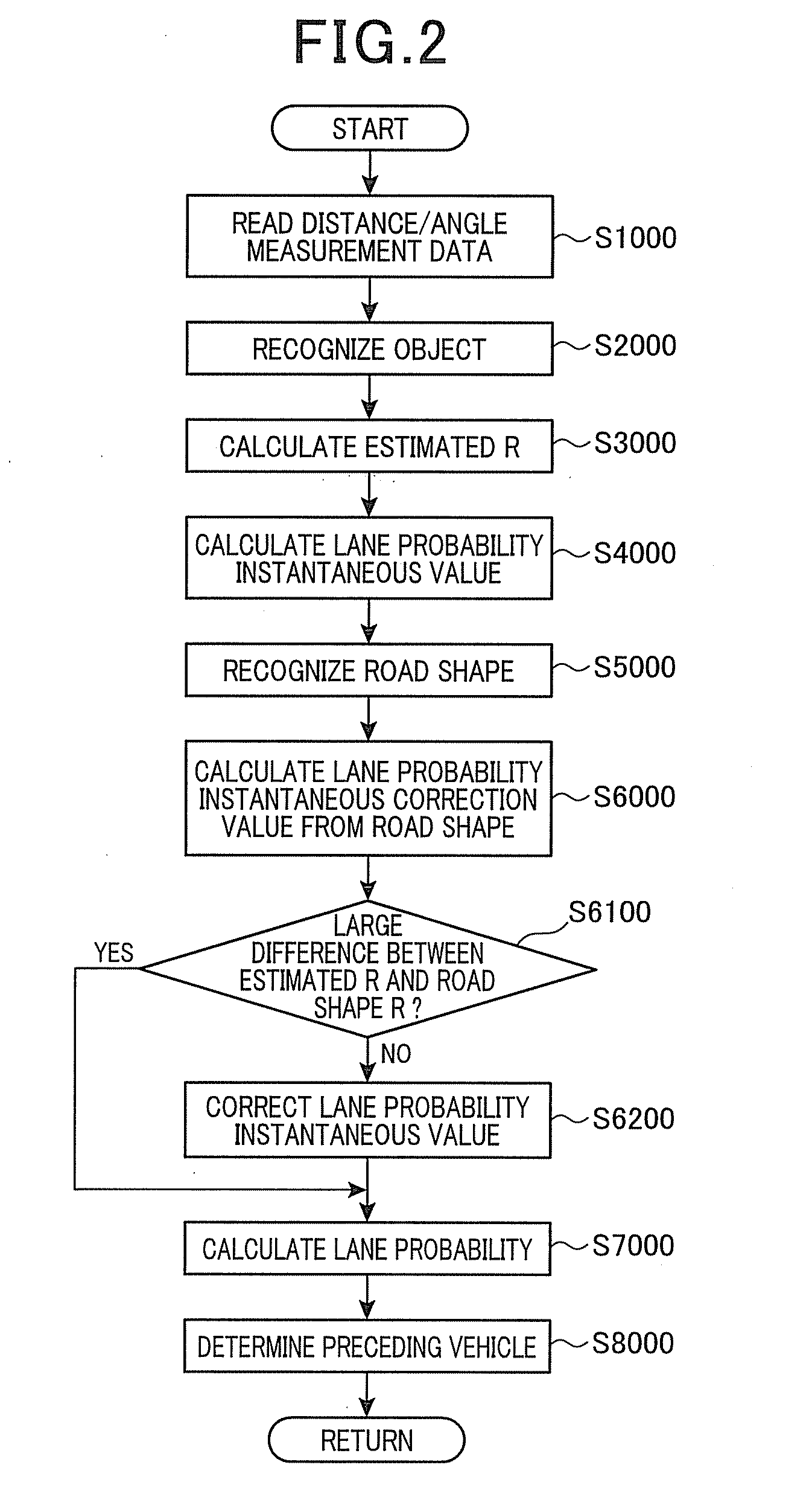
[0312]Referring to the flow diagram shown in FIG. 18, herein after is described an operation involved in the road shape recognition. At an initial step S1000 shown in FIG. 18, distance / angle data is read by the distance / angle measuring device 5. Specifically, the distance / angle measuring device 5 acquires distance / angle data corresponding to one scan. In this case, the scanning cycle is 100 msec and thus the distance / angle measuring device 5 acq...


PUM


Abstract

An example of recognition of the shape of a road where a vehicle travels is provided. An object type as to whether an object is a moving or stationary object is determined according to a relative speed of the object and a speed of the vehicle. Object-unit data effective for recognizing a road shape is extracted according to the determination. The object-unit data is used for forming data of a roadside object group, based on which a road edge is recognized. A series of the processes is repeatedly performed at a predetermined cycle. After the extraction process, a data addition process is performed to add object-unit data obtained in the extraction process of the previous cycle to object-unit data obtained in the extraction process of the present cycle. In a recognition process, a road edge is recognized according to the object-unit data obtained in the data addition process.

Description

CROSS-REFERENCE TO RELATED APPLICATION[0001]This application is based on and claims the benefit of priority from earlier Japanese Patent Application No. 2011-061860 filed Mar. 21, 2011 and Nos. 2011-110221, 2011-110222, 2011-110223, 2011-110224 and 2011-110225 all filed May 17, 2011, the descriptions of which are incorporated herein by reference.BACKGROUND OF THE INVENTION[0002]1. Technical Field of the Invention[0003]The present invention relates to a method and an apparatus for recognizing the shape of a road on which the vehicle travels.[0004]2. Related Art[0005]Methods of calculating a lane-probability instantaneous value are well known. The term lane probability refers to a probability that a target to be recognized ahead of the vehicle is present on the same lane. A lane-probability instantaneous value is calculated from a curve radius of the road where the vehicle travels in order to make a determination on an object to be controlled. The curve radius is obtained from a posit...

Claims


Application Information

Patent Timeline
Patent Type & Authority Applications(United States)
IPC IPC(8): G06F17/00
CPCB60W50/14B60W2550/306B60W10/10B60W10/184B60W30/12B60W30/16B60W40/072B60W2050/143B60W2420/62B60W2510/0604B60W2520/10B60W2520/14B60W2540/12B60W2540/18B60W10/06B60W2554/4041
Inventor SAMUKAWA, YOSHIENOZAWA, TOYOHITOSAKAMOTO, MAIOOKATA, HIROSHI
Owner DENSO CORP
Why Eureka
Try Eureka