
Lidar methods and apparatus

a technology of methods and apparatus, applied in the field oflidar methods and apparatus, can solve the problems of the main cause of death/injury of our soldiers, the improvised explosive device (ied), etc., and achieve the effect of improving the accuracy of the system in calculating

Inactive Publication Date: 2012-11-01
HODGE BRUCE
View PDF10 Cites 40 Cited by
  • Summary
  • Abstract
  • Description
  • Claims
  • Application Information

AI Technical Summary

Benefits of technology

[0011]The location of impact of the projectile may be calculated relative to a target. Also, the location of discharge of the projectile from a source, such as a shooter may be calculated. The trajectory and impact location of a second projectile may be calculated using the pulsed laser light beams, laser sensor, and at least one microprocessor. A third position of the projectile may be determined using an additional pulsed laser transmitter and sensor and the trajectory of the projectile may be calculated based upon or using this third position. Additional pulsed laser transmitters may emit laser pulses at times in between laser pulses from other laser transmitters to improve accuracy of the system in calculating projectile location and / or trajectory.

Problems solved by technology

Improvised Explosive Device's (IED's) are the main cause of death / injury to our soldiers.

Method used


Image

  • Lidar methods and apparatus
  • Lidar methods and apparatus
  • Lidar methods and apparatus

Examples


Embodiment Construction

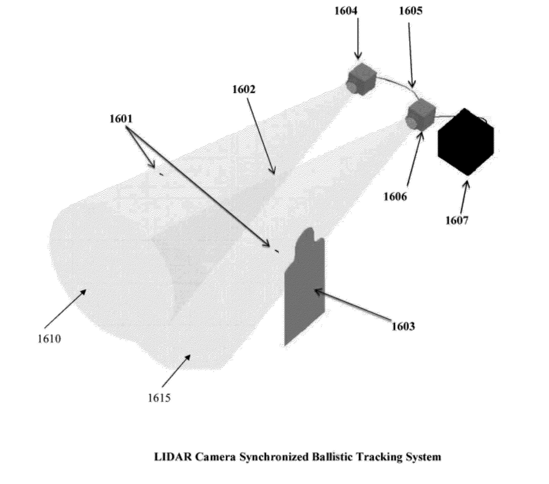
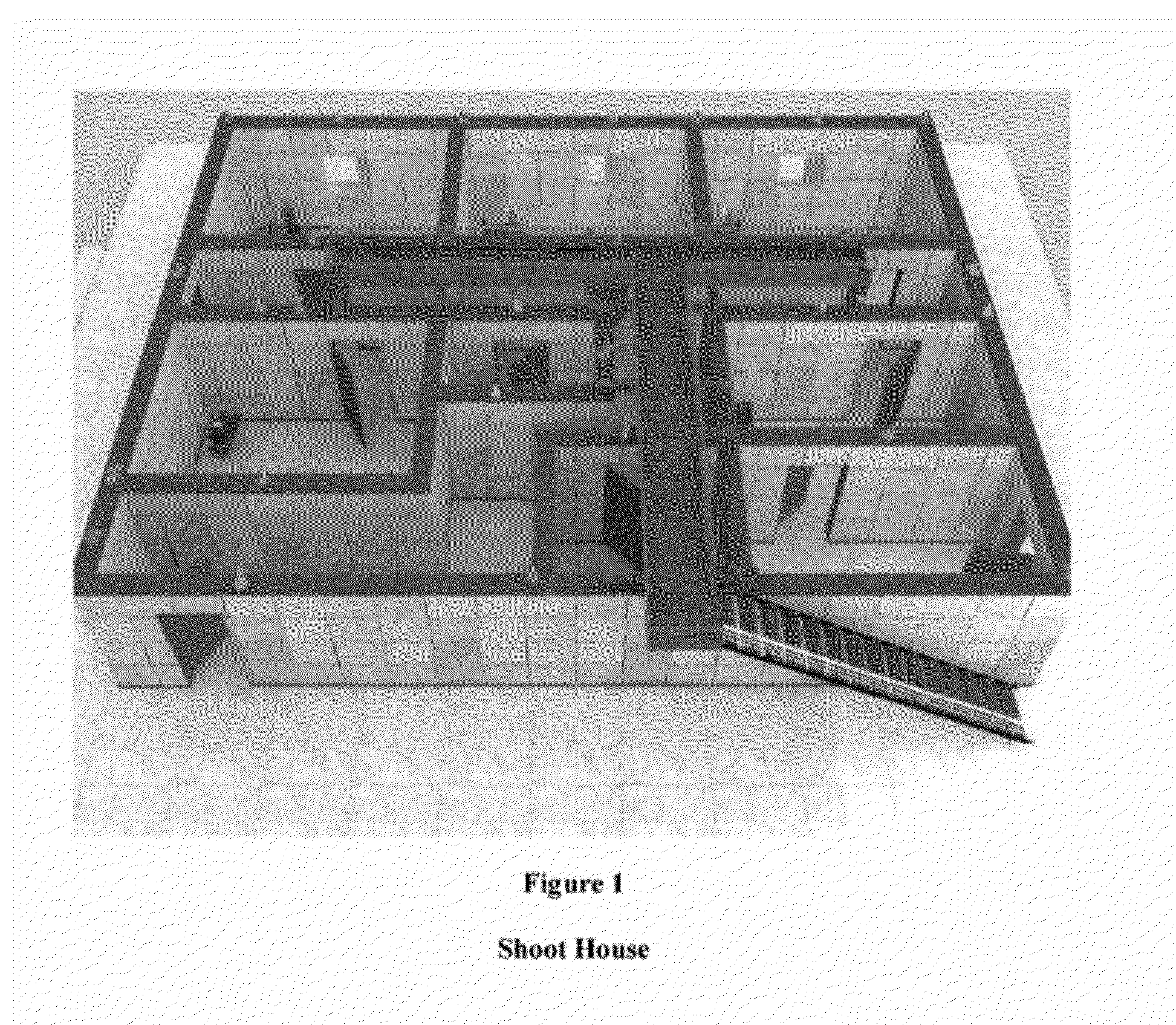
[0031]FIG. 1 shows a typical shoot house where a 3D laser sensing system (LIDAR) is used in both the rooms and hallways to detect the presence of shoots and tract projectile trajectories relevant to targets to determine the lethality of target impact. Both live fire and non-live fire projectiles, such as paintball, simunition, etc may be detected and tracked using such a LIDAR system. 3D LIDAR technology may also be used to locate the shooter positional information, control a response of interactive targets, determine an origin (i.e., original location) of a shooter (in multi-shooter scenario) and where to orientate a rotating pop-up mannequin target and / or point shoot back devices in order to engage an active threat. The LIDAR system described above, and those described below, may be one according to U.S. Pat. Nos. 6,133,989 & 6,414,746 describe which can detect objects using a diffused pulsed laser beam and an optic sensor.

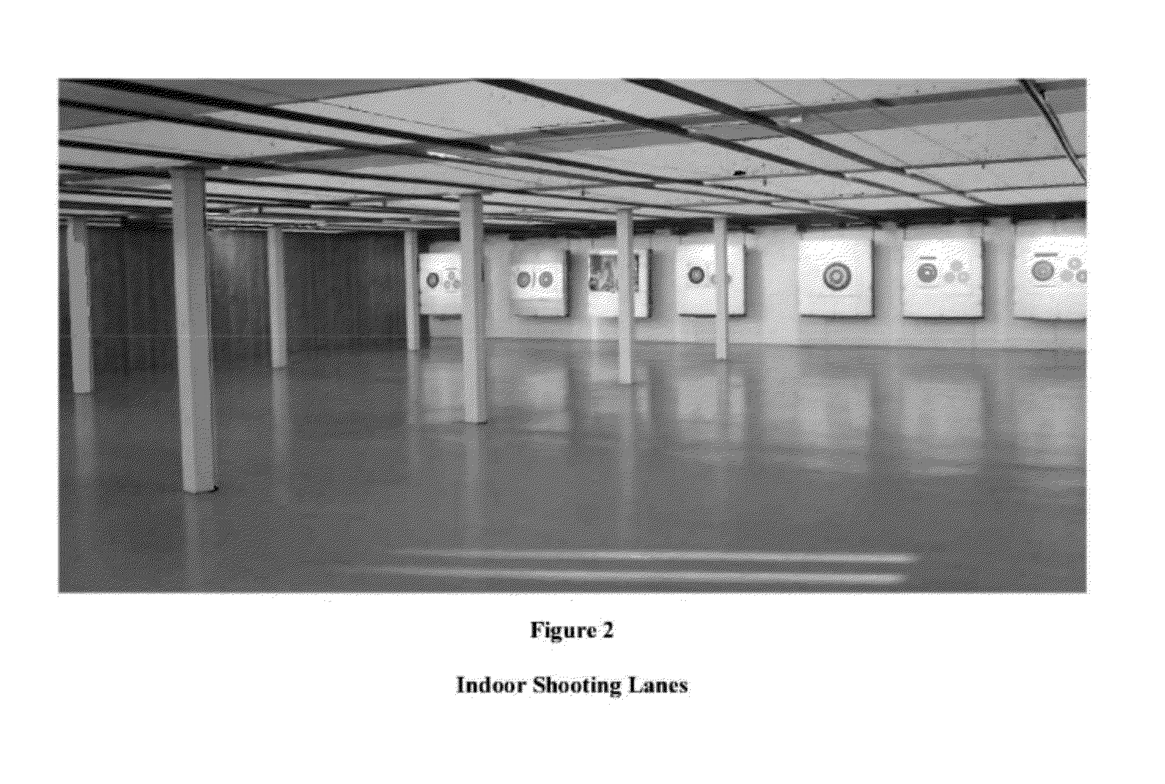
[0032]FIG. 2 shows an indoor shooting range where one or m...


PUM


Abstract

A system for detecting the trajectory of a projectile includes at least one pulsed laser transmitter configured to transmit pulsed laser light beams over a three dimensional area. At least one sensor is configured to sense the pulsed laser light beams reflected off of the projectile. A microprocessor is coupled to the laser transmitter and laser sensor to calculate a first position of the projectile at a first time based upon the first pulsed laser light beam reflected off the projectile and sensed by the laser sensor. A microprocessor calculates a second position of the projectile at a second time based upon a second pulsed laser light beam reflected off the projectile and sensed by a laser sensor. A microprocessor calculates the trajectory of the projectile based upon the first projectile position and the second projectile position and the time differences between these positions.

Description

CROSS REFERENCE TO RELATED APPLICATIONS[0001]This application claims priority to U.S. Provisional Application No. 61 / 468,433 filed Mar. 28, 2011, entitled “TARGET SYSTEM METHODS AND APPARATUS”, and U.S. Provisional Application No. 61 / 603,084 filed Feb. 24, 2012, entitled “PRECISION TARGET AND DISTURBANCE RECOGNITION METHODS AND APPARATUS”. This application is related to U.S. Utility Patent Application No. 13042351-PCT 11 / 27426 patent Filed on Mar. 7, 2011, entitled “TARGET SYSTEM METHODS AND APPARATUS”. This application is also related to U.S. Pat. No. 5,516,113, U.S. Pat. No. 7,207,566 and U.S. Pat. No. 7,862,045. The entire contents of the patents and applications mentioned in this paragraph are incorporated herein by reference.COPYRIGHT NOTICE[0002]A portion of the disclosure of this patent document contains material which is subject to copyright protection. The copyright owner has no objection to facsimile reproduction by anyone of the patent document or the patent disclosure, a...

Claims


Application Information

Patent Timeline
IPC IPC(8): G01P3/36
CPCF41J5/02F41G3/26G01S17/58G01S17/42
Inventor HODGE, BRUCE
Owner HODGE BRUCE
Features
  • Generate Ideas
  • Intellectual Property
  • Life Sciences
  • Materials
  • Tech Scout
  • Unparalleled Data Quality
  • Higher Quality Content
  • 60% Fewer Hallucinations
Learn More