Precision parabolic mirror structures

a parabolic mirror and precision technology, applied in the field of concentrated mirrors, can solve the problems of inability to adjust the shape in real-time, complex and costly conventional methods for fabricating precision parabolic mirrors, and inability to rapidly deploy and portable systems

Inactive Publication Date: 2012-11-01
KING FAHD UNIVERSITY OF PETROLEUM AND MINERALS +1
View PDF13 Cites 8 Cited by
  • Summary
  • Abstract
  • Description
  • Claims
  • Application Information

AI Technical Summary

Benefits of technology

[0009]In yet another aspect of the invention, a parabolic mirror includes a flexible material with a reflective surface and a rear surface. A flexible band is in contact with the rear surface of the flexible material. The bending stiffness of the band as a function of distance along its length is selected so that the band and the flexible material in contact therewith assume a parabolic shape when ends of the b...

Problems solved by technology

Mirror precision is important and conventional methods to fabricate precision parabolic mirrors are complex and costly.
However, they are often heavy and complex, which makes them unsuitable for rapidly deployable and portable systems.
Moreover, their shape cannot be adjusted in real-time to compensate for thermal variations, etc.
ed. While this approach can achieve the desired result, it requires far more forces than the 11 shown to achieve a smooth parabolic shape, and the implementation of the applied forces in a real system is very comp

Method used


Image

  • Precision parabolic mirror structures
  • Precision parabolic mirror structures
  • Precision parabolic mirror structures

Examples


Embodiment Construction

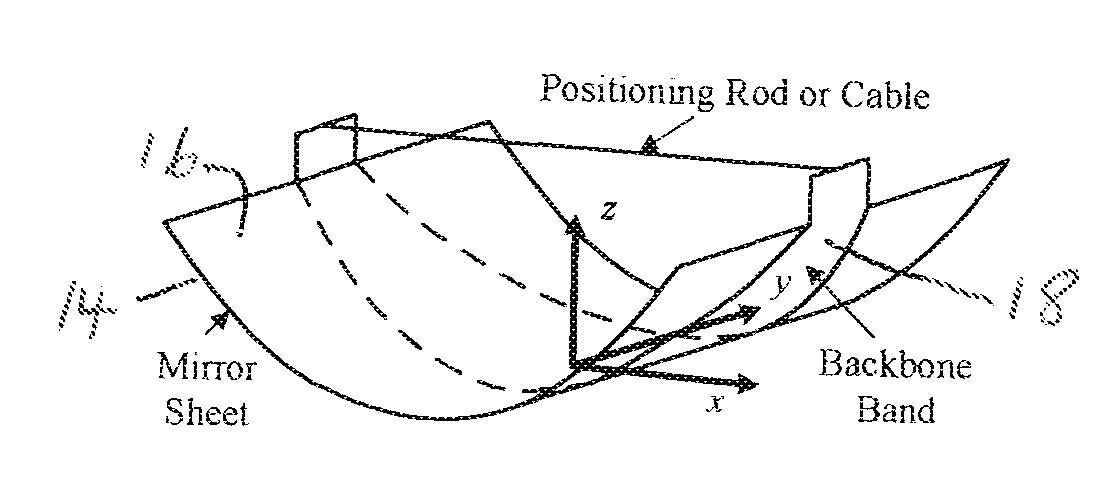
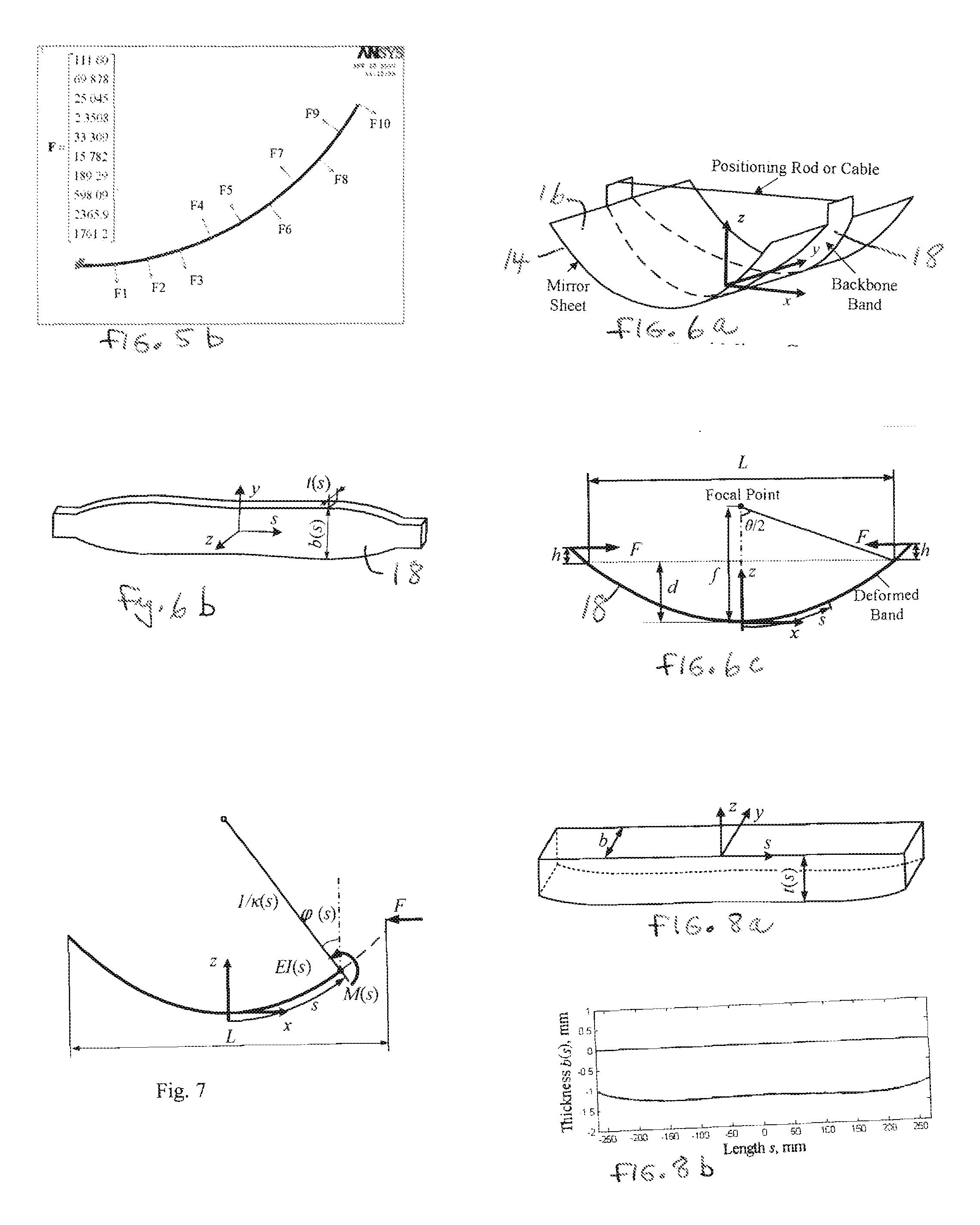
[0042]The approach presented herein for designing and fabricating precision parabolic mirrors as shown in FIG. 6a consists of a thin, flat, very flexible metal sheet 14 with a highly reflective surface 16 and a “backbone” band 18 attached to its rear surface. The figure of the “backbone” band 18 is optimized to form the sheet 14 into a precision parabola when the two ends of the band 18 are pulled toward each other by a predetermined amount. This result can be achieved using a simple spacer rod or an active position control system when high precision requires real-time adjustment.

[0043]An analytical model is used to optimize the band's shape after it is deformed so that it is parabolic. The band 18 is cut from a flat plate with a stiffness that is substantially higher than the mirror sheet 14. As discussed below, the elastic properties of the band 18 can also be tuned to account for the mirror plate's stiffness.

[0044]It is also shown herein that the band 18 profile can be determined...


PUM

PropertyMeasurementUnit
Lengthaaaaaaaaaa
Lengthaaaaaaaaaa
Lengthaaaaaaaaaa

Abstract

Parabolic Mirror. The mirror includes a flexible material with a reflective surface and a rear surface. A flexible band is in contact with the rear surface of the flexible material. The bending stiffness of the band as a function of distance along its length is selected so that the band and the flexible material in contact therewith assume a parabolic shape when ends of the band are moved toward one another. In a preferred embodiment, the bending stiffness of the band is achieved by controlling the second moment of area of the band along its length. The second moment of area may be adjusted by altering the width of the band along its length or by altering the thickness of the band along its length, or a combination of the two.

Description

BACKGROUND OF THE INVENTION[0001]This invention relates to concentrator mirrors and more particularly to methodology and structure for shaping such a mirror into a parabolic shape using a band having a selected bending stiffness along its length.[0002]Solar mirror collectors are a major subsystem of many solar energy systems, particularly for solar thermal generators [1]. Numbers in brackets refer to the references included herewith. The contents of all of these references are incorporated herein by reference in their entirety. Large thermal systems may use many collectors covering large sites [2], as shown in FIG. 1. Collectors generally consist of concentrating parabolic mirrors 10, an absorber tube 12 and a supporting structure, which is often equipped with a solar tacking mechanism. They are called parabolic trough collectors (PTCs) [2], and are shown in schematic form in FIG. 2.[0003]The parabolic shaped mirror 10 (reflector) focuses the sunlight onto a linear tube 12 located a...

Claims


Application Information

Patent Timeline
IPC IPC(8): G02B5/10B32B3/02B32B3/30B32B3/00F24S23/74
CPCG02B5/10F24J2/145Y02E10/45Y10T428/24479Y10T428/24612Y10T428/24777Y10T428/24F24S23/745Y02E10/40
Inventor LI, LIFANGDUBOWSKY, STEVENKECSKEMETHY DARANYI, ANDRES GEORGEARIF, ABUL FAZAL M
Owner KING FAHD UNIVERSITY OF PETROLEUM AND MINERALS
Why Eureka
Try Eureka