

Image forming apparatus
a technology of image forming and forming parts, which is applied in the direction of electrographic process equipment, instruments, optics, etc., can solve the problems of affecting the operability of users to use the apparatus, and achieve the effect of reducing the distance between the exposure unit and the image forming
- Summary
- Abstract
- Description
- Claims
- Application Information
AI Technical Summary
Benefits of technology
Problems solved by technology
Method used
Image

Examples
first modification
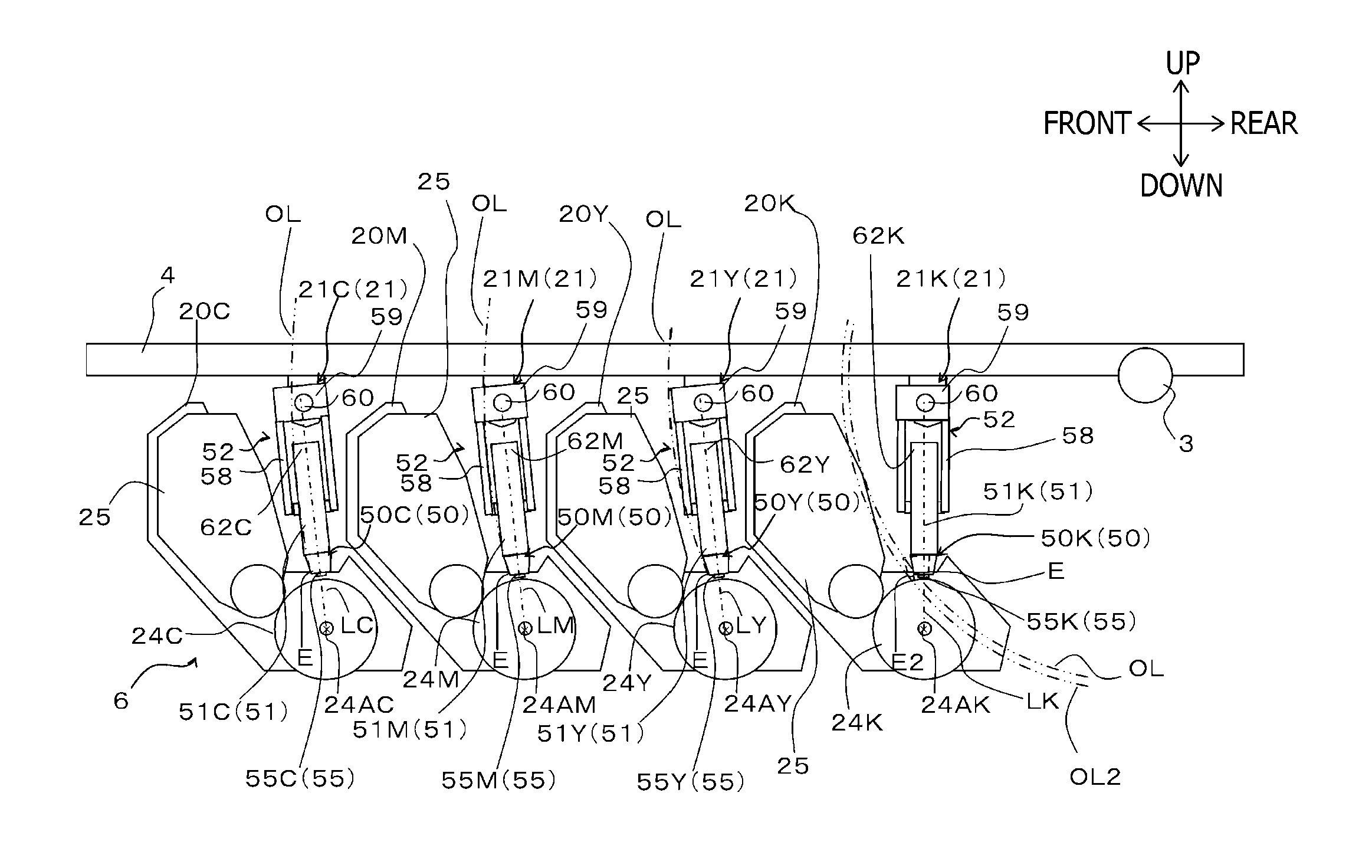
[0063]Subsequently, an explanation will be provided about a first modification according to aspects of the present invention with reference to FIG. 4. In the first modification, the exposure units 21 are provided to form respective different angles relative to the vertical direction.
[0064]Specifically, the straight lines LC, LM, LY, and LK are inclined as an LED head 50 closer to the rotational shaft 3 is more turned rearward around the rotational axis line 24A of a corresponding photoconductive drum 24. In other words, an LED head 50 closer to the rear end of the color printer 1 has a relative position, to a corresponding rotational axis line 24A, more shifted toward the rotational shaft 3.
[0065]For example, the LED head 50C is provided to the holding member 51C such that the straight line LC is inclined forward around the rotational axis line 24AC to form an angle of 6 degrees relative to the vertical direction. The LED head 50M is provided to the holding member 51M such that the ...
second modification
[0069]Subsequently, an explanation will be provided about a second modification according to aspects of the present invention with reference to FIG. 5. In the second modification, as shown in FIG. 5, the exposure unit 21K is inclined toward the rotational shaft 3 with respect to the vertical direction.
[0070]Specifically, the LED head 50K is provided to the holding member 51 such that the straight line LK is inclined toward the rotational shaft 3 around the rotational axis line 24A with respect to the vertical direction. In the second modification, the straight line LK is inclined toward the rotational shaft 3 at an angle of 6 degrees relative to the vertical direction. The straight lines LC, LM, and LY are inclined in the same manner as the aforementioned embodiment. Namely, the straight lines LC, LM, and LY are inclined forward at an angle of 6 degrees around the respective rotational axis lines 24A. Thereby, the farthest portion E of the LED head 50K is made closer to the rotation...
third modification
[0074]Subsequently, an explanation will be provided about a third modification according to aspects of the present invention with reference to FIG. 6. In the third modification, as shown in FIG. 6, the exposure unit 21K is inclined toward the rotational shaft 3 with respect to the vertical direction.
[0075]Specifically, the LED head 50K is provided to the holding member 51 such that the straight line LK is inclined toward the rotational shaft 3 around the rotational axis line 24A with respect to the vertical direction. In the third modification, the straight line LK is inclined toward the rotational shaft 3 at an angle of 6 degrees relative to the vertical direction. Thereby, the farthest portion E of the LED head 50K is separated farther from the process unit 20K. The straight lines LC, LM, and LY are inclined in the same manner as the aforementioned embodiment. Namely, the straight lines LC, LM, and LY are inclined forward at an angle of 6 degrees around the respective rotational a...
PUM
 Abstract
Description
Claims
Application Information